www.ti.com
Features
1 Features
• Complete evaluation system for the bq77910A 4-cell to 10-cell Li-Ion and Li-Polymer battery protector
• Populated circuit module for 10-cell parallel FET configuration for quick setup
– Pads for components for configuration of additional cell counts and series FETs
• Power connections available on terminal blocks or banana jacks
• Control and status signals available on terminal blocks
• Resistor cell simulator for quick setup with only a power supply
• PC software available for configuration
1.1 Kit Contents
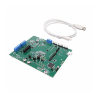
• bq77910A circuit module
• Resistor cell simulator
• Set of support documentation
Table 1. Ordering Information
EVM Part Number Chemistry Configuration Capacity
bq77910AEVM-001 Li-Ion 10 cells Any
NOTE: Although capacity is shown as "Any," practical limits of the physical construction of the
module will typically limit the operation of the EVM to a 1P or 2P battery construction. Refer
to the physical construction section for board details.
1.2 Required Equipment
The following equipment is required to operate the bq77910A EVM in a simple demonstration:
• DC power supply, 0-43V at 0.5A
• DC voltmeter or oscilloscope
• DC power supply, ~3V at .1A or an approximately 15k-Ω 1/4W resistor
• Test leads to connect equipment
The following equipment is required to operate the bq77910A with a more extensive demonstration:
• TI USB-TO-GPIO interface adapter
• Computer with USB port and compatible Windows 32 bit operating system
• Electronic load
• Additional power supplies
• TI bq77908-10-GUI-SW Evaluation Software (see Section 4)
2 bq77910A Circuit Module and Interfaces
The bq77910A circuit module contains the bq77910A IC and related circuitry to demonstrate the features
of the IC. A FET with heatsink is provided for the high current discharge path. A lower current FET is
provided for the charge path. A thermistor provides temperature sensing for the device. Other components
provide support for the IC and connections to the board.
2.1 Circuit Module Connections
Connections are provided for the following interfaces:
• Direct cell connections
• PACK connections
• Programming interface
3
SLUU855–February 2012 bq77910AEVM
Submit Documentation Feedback
Copyright © 2012, Texas Instruments Incorporated

 Loading...


