www.ti.com
7.10 Reserved Pins .................................................................................................... 22
7.11 Flag Outputs ...................................................................................................... 22
7.12 Thermal Sensor ................................................................................................... 22
7.13 ZEDE ............................................................................................................... 22
7.14 Programming Interface .......................................................................................... 22
8 bq77910A Circuit Module Physical Construction ...................................................................... 23
8.1 Main Board ........................................................................................................ 23
8.2 Resistor Cell Simulator .......................................................................................... 32
List of Figures
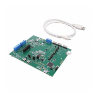
1 Basic EVM Setup ........................................................................................................... 7
2 Successfully Updated TI USB Interface Adapter ....................................................................... 9
3 EVM Connection for Communication and Programming............................................................. 11
4 GUI with Communication Established .................................................................................. 12
5 Communication Selection Window...................................................................................... 13
6 Commands Without Communication Established..................................................................... 13
7 Register Section ........................................................................................................... 14
8 Status Section.............................................................................................................. 16
9 Polling Status with Under-Voltage Condition .......................................................................... 16
10 Top Silkscreen ............................................................................................................. 23
11 Top Assembly.............................................................................................................. 24
12 Top Layer................................................................................................................... 24
13 Layer 2...................................................................................................................... 25
14 Layer 3...................................................................................................................... 25
15 Bottom Layer............................................................................................................... 26
16 Bottom Silkscreen ......................................................................................................... 26
17 Bottom Assembly.......................................................................................................... 27
18 Schematic Diagram Page 1.............................................................................................. 30
19 Schematic Diagram Page 2.............................................................................................. 31
20 Resistor Simulator Top Silkscreen ...................................................................................... 32
21 Resistor Simulator Top Layer............................................................................................ 33
22 Resistor Simulator Bottom Layer........................................................................................ 34
23 Resistor Simulator Top Assembly....................................................................................... 35
24 Resistor Simulator Bottom assembly ................................................................................... 36
25 Resistor Simulator Schematic Diagram ................................................................................ 38
List of Tables
1 Ordering Information........................................................................................................ 3
2 Cell Connections ............................................................................................................ 4
3 PACK Connections ......................................................................................................... 4
4 Programming Interface Connections ..................................................................................... 4
5 Test Header Signals........................................................................................................ 5
6 Control and Status Connections .......................................................................................... 5
7 Adapter Cable Pinout ..................................................................................................... 10
8 Status Section Indicator Colors.......................................................................................... 16
9 Cell Count Component Configuration................................................................................... 19
10 bq77910A Circuit Module Bill of Materials ............................................................................. 28
11 Performance Specification Summary ................................................................................... 32
12 Resistor Simulator Bill of Materials...................................................................................... 36
2
bq77910AEVM SLUU855–February 2012
Submit Documentation Feedback
Copyright © 2012, Texas Instruments Incorporated
 Loading...


