EasyManua.ls Logo

Texas Instruments bq77910AEVM User Manual

Texas Instruments bq77910AEVM
48 pages
To Next Page IconTo Next Page
To Previous Page IconTo Previous Page
Page #14 background imageLoading...
Page #14 background image
Software Operation
www.ti.com
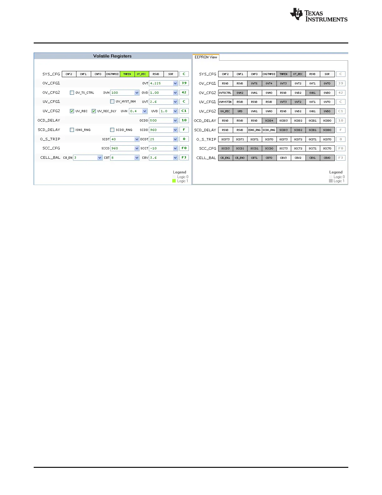
Figure 7. Register Section
The Read Volatile Registers command will read the values from the registers in the part and display them
in the GUI window. When a part is first powered, these will typically be zero. When connecting to a
powered part, they will likely contain residual values.
The Read EEPROM Registers command will read the EEPROM values from the device and display them
in the EEPROM registers section of the window for viewing. This is a viewing operation and data
manipulation is not allowed in the displayed EEPROM data.
The Read All Registers command reads both the volatile and EEPROM registers from the device and
displays the values.
The Copy EEPROM to Volatile command will copy the EEPROM register values to the corresponding
volatile registers and display both in the GUI. This is a good starting point for making incremental changes
to the device settings.
The Verify Volatile Registers command checks whether the volatile registers match the contents of the
device. This can be useful as a check before programming the EEPROM.
The Program EEPROM command will write the volatile register values.
5.1.4 File Menu
The Load Registers from File command will read a properly formatted file and fill the volatile register
section with the values. This is useful to load a device with a saved configuration. A windows navigation
tool allows selection of the file. While files could be edited, it is recommended to load files saved by the
software, and if any editing is performed on the file, check all values before programming the device.
The Save Registers to File command will create a file. A windows navigation tool allows selection of the
location and file name. Files have the .cfg extension.
The Exit command will exit the program.
5.2 Working with Register Values
When the software initially connects to a device it will copy that device's EEPROM to its volatile registers
and display those results. Since the device does not know if power has been lost to the device, the
register display may be stale. If the device has been changed or power cycled to the part, the registers
should always be read before making changes. If a file is loaded with values matching the displayed
values, the software will not know the data is different from the part. Reading the registers or copying
EEPROM values to the volatile registers is recommended before any change.
14
bq77910AEVM SLUU855February 2012
Submit Documentation Feedback
Copyright © 2012, Texas Instruments Incorporated

Table of Contents

Question and Answer IconNeed help?

Do you have a question about the Texas Instruments bq77910AEVM and is the answer not in the manual?

Texas Instruments bq77910AEVM Specifications

General IconGeneral
TypeEvaluation Module
Part Numberbq77910AEVM
Battery ChemistryLi-ion
ManufacturerTexas Instruments
Operating Temperature Range-40°C to 85°C
DescriptionEvaluation Module for bq77910A Battery Protection IC
FunctionBattery Protection
Number of Series Cellsup to 10
Protection FeaturesOvervoltage

Summary

Features

Required Equipment

Specifies necessary external hardware for EVM operation.

bq77910A Circuit Module and Interfaces

Signal Descriptions

Explains the signals available on the EVM and their purpose.

EVM Hardware Connection and Operation

Connecting the Cell Simulator

Instructions for connecting the cell simulator board to the EVM.

Basic Operation

Step-by-step guide for basic EVM operation with the cell simulator.

Software Installation

System Requirements

Outlines the necessary computer specifications for the evaluation software.

TI USB Interface Adapter

Detailed steps for setting up the TI USB-TO-GPIO adapter.

Aardvark Adapter

Information on using the Total Phase Aardvark adapter with the EVM.

Installing Evaluation Software

Procedure for installing the bq77908-10-GUI-SW evaluation software.

Software Operation

Menu Commands

Overview of commands available in the evaluation software interface.

Working with Register Values

Explains how to read, write, and manage device register values.

Status Section

How to use the status section to monitor fault conditions and device status.

Circuit Description and Configuration

Cell Monitor Inputs

Details the RC filter network for cell voltage monitoring.

FET Circuits

Describes the power FET configurations for discharge and charge paths.

Programming Interface

Details the serial communication interface for programming the device.

Physical Construction and Bill of Materials

Main Board Layout

Provides visual representation of the main board component placement and layout.

Circuit Module Bill of Materials

Lists all components used in the bq77910A circuit module assembly.

Resistor Cell Simulator

Details the design and components of the resistor cell simulator.

EVM Warnings and Disclaimers

Regulatory Compliance Information

Related product manuals