Software Operation
www.ti.com
During programming the software checks that the device volatile registers match the values shown. If they
do not match, an error message is displayed. Continuing with programming when the values do not match
will unexpectedly alter the configuration of the device. If the error is displayed it is recommended to read
the volatile registers to examine the contents, correct any communication error and re-start the software or
device as needed for proper programming.
5.3 Status Section
The status section of the GUI is shown in Figure 8. This section allows the user to display internal status
registers of the devices fault condition. This data is not part of normal operation of the device and is not
shown in the data sheet. Accessing the data is disruptive to the device, however it can be beneficial in
evaluation.
Figure 8. Status Section
The status is read by selecting the Polling "Enable" button on the left side of the status section. This will
periodically set ZEDE high to the device, read the status registers, and return ZEDE low. The polling
period can be selected with the drop down box next to the button. The button function and label change to
"Disable". The button label indicates the action of the next button actuation.
A consequence of polling is that a pending fault delay will be terminated by the status read. Polling is
typically independent of any system change and a fault may be recorded as soon as the poll occurs. This
may lead to unexpected results in evaluation. The following describe a couple examples which may occur:
• The user has selected a 2 second under voltage delay and wants to observe the timing on a scope.
The user leaves polling active and decreases the device voltage. The poll occurs just after the voltage
drops and the zero delay causes the fault to be registered. The FETs turn off and the user thinks the
delay setting is not working. The situation here is the poll set ZEDE high and terminated the under
voltage delay.
• The user is polling status to watch faults. CHGST is tied high to prevent the part from shutting down
due to under voltage. The user begins switching currents and is surprised when a SCC fault occurs.
Observing the sense resistor voltage, the user does not see a charge current. The situation here is the
poll set zero delay and eliminates noise filtering on the current. The SCCT is typically a low and thus
most sensitive to any noise; having CHGST high prevents recovery from the fault.
The values display in several colors. See Table 8.
Table 8. Status Section Indicator Colors
Color Meaning
gray status is not read
device is polling and status is normal with connected device, or adapter is not
bright green
connected
bright red device is polling and status is fault
dark green or dark red device is not polling and value is residual from last poll
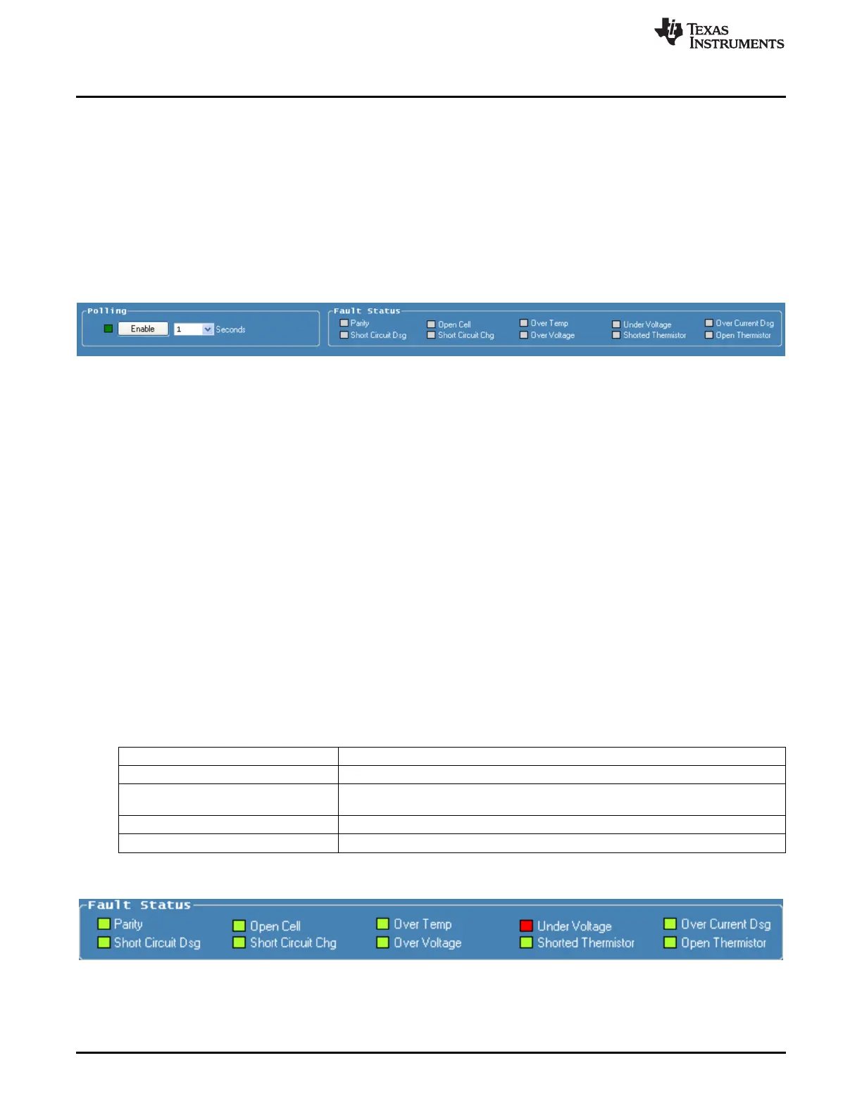
Figure 9 shows a typical status display polling with undervoltage.
Figure 9. Polling Status with Under-Voltage Condition
16
bq77910AEVM SLUU855–February 2012
Submit Documentation Feedback
Copyright © 2012, Texas Instruments Incorporated