www.ti.com
bq77910A EVM Hardware Connection and Operation
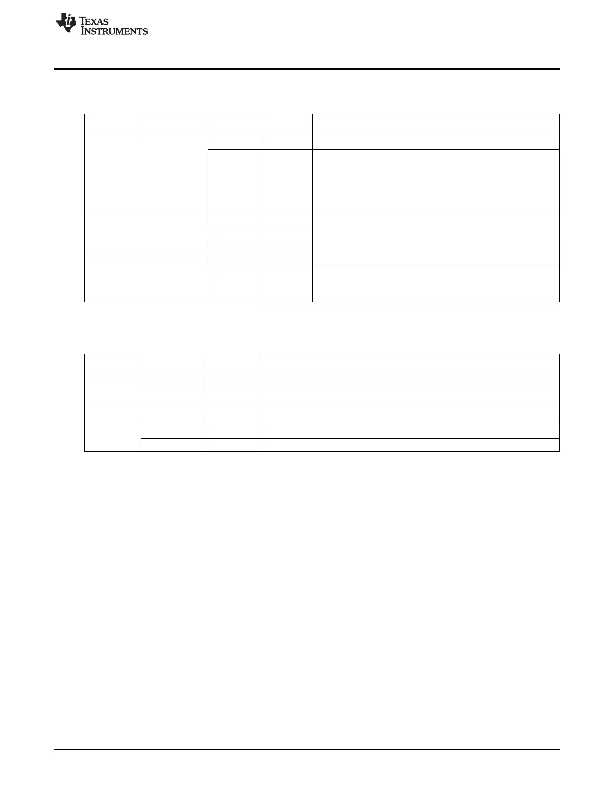
Test header or pattern signals are described in Table 5.
Table 5. Test Header Signals
Reference
Usage Pin Number Signal Description
Designator
J1 Default: shunt 1 Battery feed Power feed to 100-Ω shunt resistor
installed for
2 BAT Output of 100-Ω shunt resistor to IC BAT pin
normal
operation.
Remove shunt
for U1 supply
current
measurement
J6 Default: no 1 VREG IC regulator output
shunt. Install
2 ZEDE IC zero delay test point and input pin, also connected to J3
shunt to hold
3 PD Pull down resistor for strong pull down of ZEDE if required
ZEDE high
J8 Not populated. 1 TS IC temperature sense pin
Alternate test
2 GND Signal reference for the IC
point or remote
thermistor
connection
Control and status signals are provided on terminal blocks. These signals are described in Table 6.
Table 6. Control and Status Connections
Reference
Pin Number Signal Description
Designator
J7 1 TS IC TS signal through a resistor
2 GND Signal reference for the IC
J9 1 CHGCTL Control signal for charger detection, connects through a resistor to the IC CHGST
pin
2 DSGFLAG Diode and resistor isolated DSG signal
3 CHGFLAG Diode and resistor isolated CHG signal
3 bq77910A EVM Hardware Connection and Operation
This section describes the connection of the circuit module and EVM and simple operation in its default
configuration.
3.1 Initial Considerations
Boards are tested after assembly with a basic functional test. This test may not check every connection on
the board. Boards should be checked for function in the user’s environment before relying on the safety
features of the board. Operation of the board with test equipment before connecting cells is recommended
and described in this document.
The default configuration of the board is 10 cells with parallel FETs. Modifying the EVM for different cell
counts or FET configuration requires solder connections. It is recommended that the user familiarize
themselves with operation of the board in the default configuration before modifying the board, and check
the operation of the board with test equipment after any modification. Configuration of the board is
described in Section 7.
Be sure to observe the cautions and warnings in this document.
A variety of connections are provided on the EVM. The manufacturer's rating for the terminal blocks for
Pack and Battery connections is 32A nominal. Parallel connections are provided for high current
operation. The banana jacks are rated at 15A. Safety agency ratings may be lower than the manufacturer
ratings, limit currents to appropriate values for your evaluation. Cell monitor terminal blocks and the
control signal terminal blocks are rated at lower currents and should not be used for high current paths.
5
SLUU855–February 2012 bq77910AEVM
Submit Documentation Feedback
Copyright © 2012, Texas Instruments Incorporated