www.ti.com
bq77910A Circuit Module Physical Construction
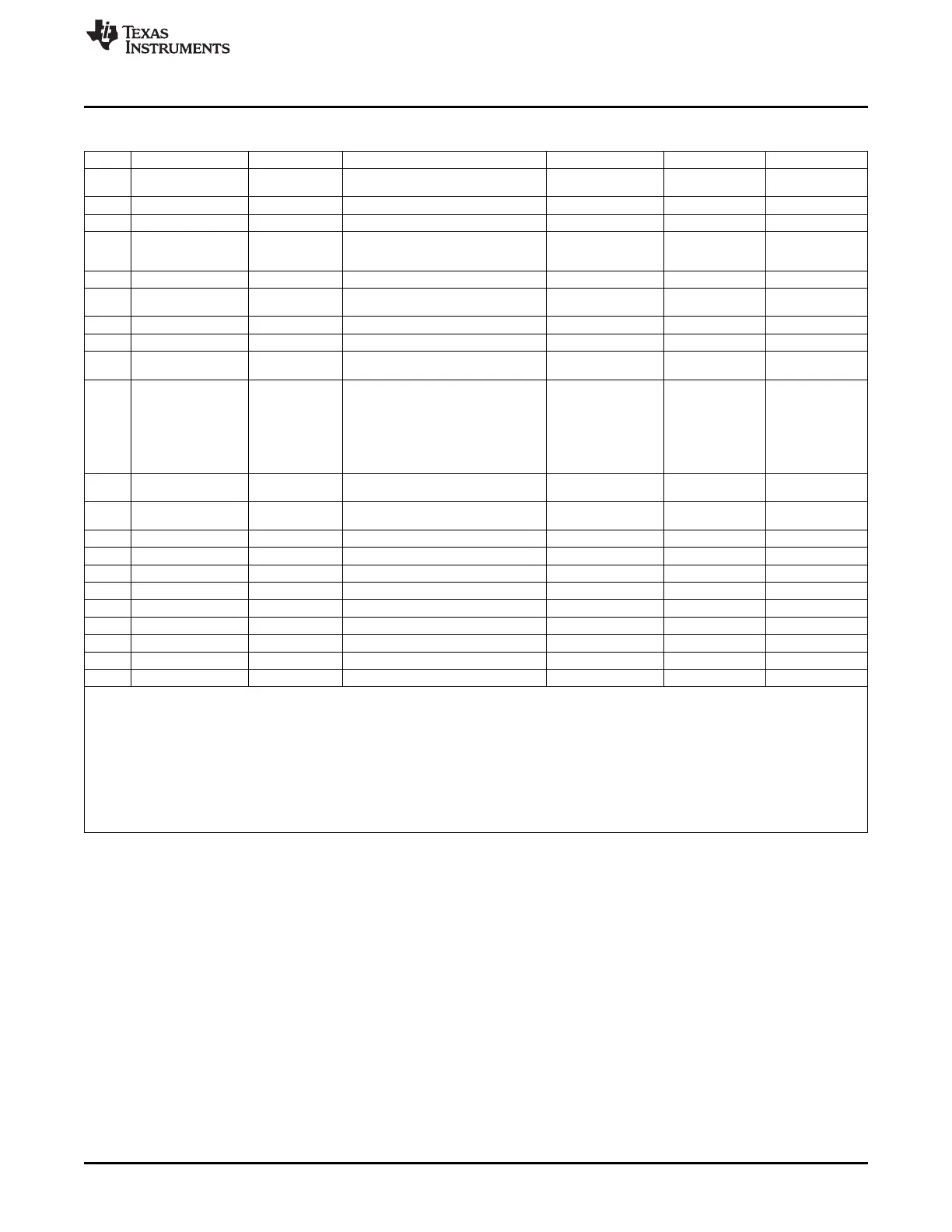
Table 10. bq77910A Circuit Module Bill of Materials (continued)
Count Reference Design Value Description Size Part Number Manufacturer
10 R5, R8, R9, R12, R13, 100 Resistor, Chip, 1/16W, 1% 0603 Std Std
R14, R15, R32, R40, R45
2 R50, R52 0.002 Resistor, 2 mΩ, 1W, 1% 2512 WSL25122L000FEA Vishay
0 R64 Resistor, Chip, 1/16W, 1% 0603
11 R7, R11, R18, R19, R20, 47 Resistor, Metal Film, 1/4 watt, ± 5% 1206 Std Std
R21, R22, R25, R26,
R29, R31
1 RT1 10k Thermistor, TH, ±1% 0.095 X 0.150 inch 103AT-2 Semitec
0 SPK1, SPK2, SPK3, Spark Gap, 0.010 inch space 0.050 x 0.070 inch
SPK4, SPK5, SPK6
0 TP37, TP49, TP51, TP52 Plated Through Hole, Dia. 0.094 0.150 x 0.150 inch
4 TP34, TP35, TP39, TP40 5020 Test Point, loop 0.100 x 0.100 inch 5020 Keystone
8 TP13, TP18, TP3, TP30, 5002 Test Point, White, Thru Hole Color Keyed 0.100 x 0.100 inch 5002 Keystone
TP38, TP41, TP47, TP48
0 TP1, TP10, TP11, TP12, Test Point, 0.020 Hole
TP14, TP17, TP2, TP21,
TP22, TP23, TP24, TP25,
TP26, TP27, TP28, TP29,
TP31, TP32, TP33, TP36,
TP4, TP42, TP43, TP45,
TP46, TP5, TP6, TP7,
TP8, TP9
0 TP15, TP16, TP19, TP20, Test Point, 0.032 Hole
TP44, TP50, TP53
1 U1 bq77910ADBT IC, Multicell Li-Ion/Lithium Polymer Pack TSSOP-38 (DBT) bq77910ADBT TI
Protection
1 – PCB, 4.7 In x 3.25 In x 0.062 In HPA462 Any
1 – Shunt, 100-mil, Black 0.100 929950-00 3M
1 – Thermal pad SP900S-0.009-00-54 Bergquist
1 – Screw, 6-32 x 0.375", pan head, Nylon Std Std
1 P4 (##) ** TERMBLOCK PLUG 5POS 3.81MM 1827156 Phoenix Contact
1 P5 (##) ** TERMBLOCK PLUG 6POS 3.81MM 1827169 Phoenix Contact
4 – Standoff, M-F threaded 6-32, 0.5", Nylon 4816 Keystone
4 – Nut, Hex, 6-32, Nylon Std Std
1 – Resistive Cell Simulator HPA582 TI
Notes: 1. These assemblies are ESD sensitive, ESD precautions shall be observed.
2. These assemblies must be clean and free from flux and all contaminants. Use of no clean flux is not acceptable.
3. These assemblies must comply with workmanship standards IPC-A-610 Class 2.
4. Ref designators marked with an asterisk ('**') cannot be substituted. All other components can be substituted with equivalent MFG's components.
5. Install thermal pad between heatsink & Q3 and secure with screw. If heatsink is substituted, use appropriate screw thread
6. Provide connectors (##) with assembly, install on J4 and J5 after test
7. Install shunt on J1 during test
8. Install standoffs at board corners, nut on top
29
SLUU855–February 2012 bq77910AEVM
Submit Documentation Feedback
Copyright © 2012, Texas Instruments Incorporated