SERVICE TROUBLESHOOTING 4-12 Manual 0-2725
Meter (+) Meter (-) Indication
(+) R2 Open
R2 (+) Open
AC1 R2 Diode Drop
R2 AC1 Open
AC2 R2 Diode Drop
R2 AC2 Open
AC3 R2 Diode Drop
R2 AC3 Open
AC1 (-) Open
(-) AC1 Diode Drop
AC2 (-) Open
(-) AC2 Diode Drop
AC3 (-) Open
(-) AC3 Diode Drop
The meter should indicate a diode drop in one direction
and an open in the other direction for each check (see
NOTE).
NOTE
Indication for R2 to (+) checks should be open in
both directions.
If Input Bridge Diode is shorted, make the following
checks with an ohmmeter at the Main Contactor:
Meter (+) Meter (-) Indication
L1 T1 Open
L2 T2 Open
L3 T3 Open
If any test has resistance, then replace the Main Contac-
tor also.
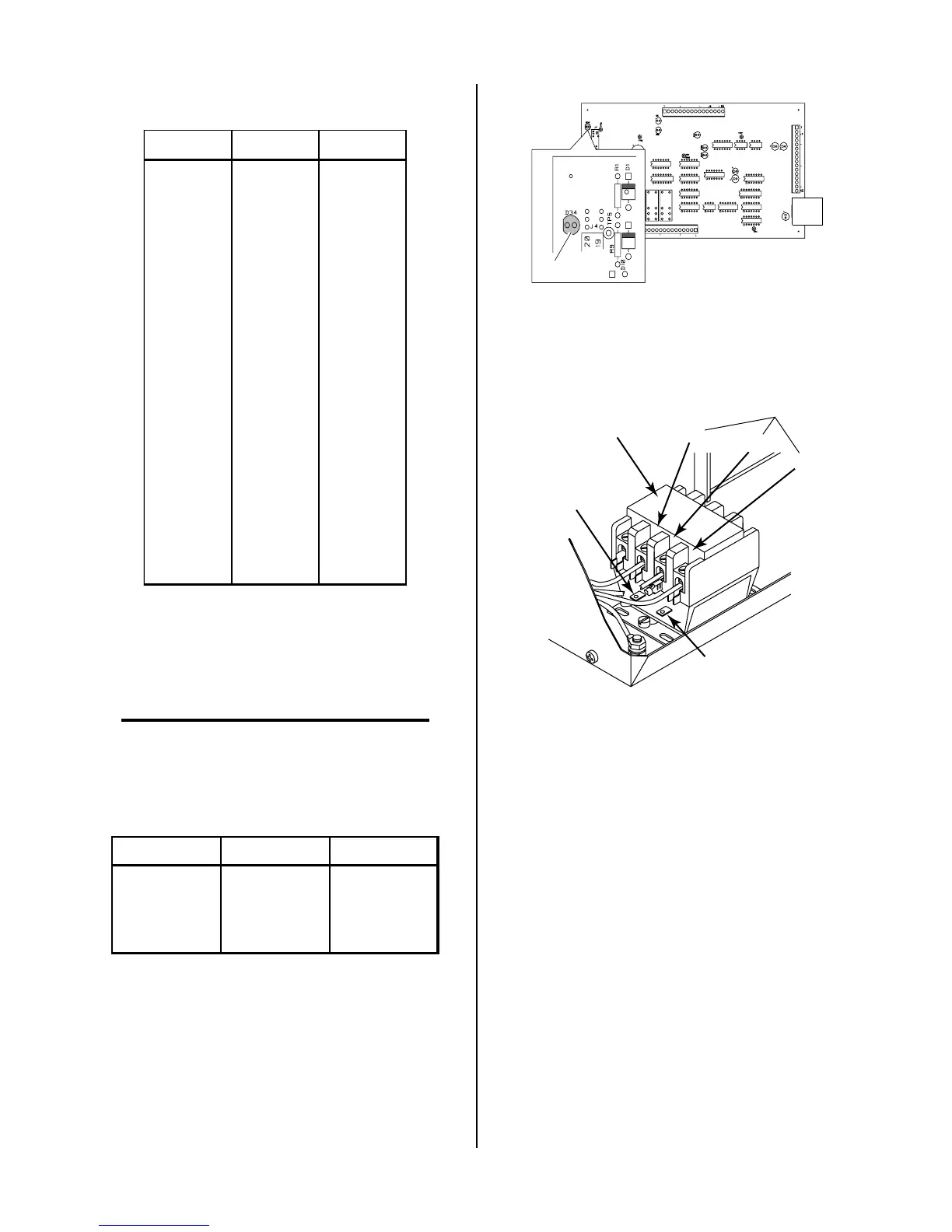
F. Main Contactor (MC1) Test
Reconnect power and observe proper start-up procedure.
Indicator D34 on the Logic PC Board should be ON. If
indicator D34 is OFF there is no voltage to the Power
Supply or an overvoltage condition exists.
A-01395
D34
If indicator D34 is OFF check for proper AC input volt-
age at L1, L2 and L3 from the EMC Filter Assembly.
L1
L2
L3
Main Contactor
(MC1)
A-01939
Coil
Wire #59
Coil
Wire #55
From EMC
Filter Assembly
Measure voltage on coil of contactor, approximately 117
VAC between wires #55 and #59.
• If voltage is correct, replace Main Contactor.
• If voltage is incorrect, replace Logic PC Board.
G. Temperature Circuit Test
Test the temperature circuit per the following:
1. Place the front panel ON/OFF switch to the OFF
position.
2. Disconnect ribbon cable from the Upper FET/
Heatsink Assembly at J6.

 Loading...


