CUTMASTER 60i
Manual 0-5475 SERVICE
5-11
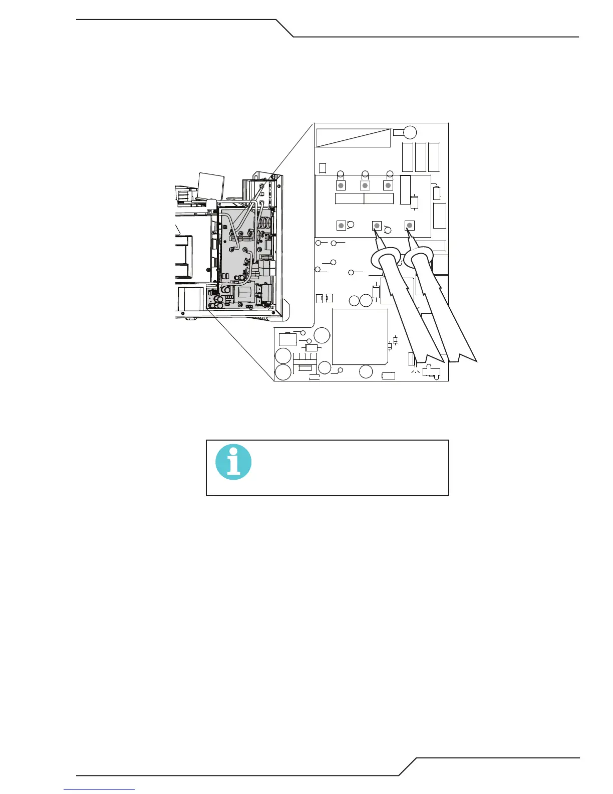
On all of these measurements measure on the terminal or the PCB pad, not the screw head. The screw has a coating
that may not be conductive.
1. Measure inrush resistors.
Set meter to Ohms scale. Measure from Bridge+ to square pad to the right of Bridge+. Normal resistance
should be 47 ohms +/- 3.
GRN/YEL
ORANGE
VIOLET
BLACK
ORANGE
BLACK
CHASSIS
GND
(3Ø ONLY)
+15V PRI
+24V
-15V
+15V
3Ø
1Ø
AC1
AC2
AC3
GND PRI
BRIDGE+
TP21
TP8 TP23
TP22
TP4
ACINSEN
HI LINE
BUS CHK
LO LINE15 UV
+
C303
D301
D303
HS300 HS301
C302
+
C300
C307
+
C306
+
C304
+
C301
D304
D306
D305
D307
1
J305
1
J304
46
13
J303
K300
MOV300 MOV301 MOV302
1
J302
Q301Q300
R300
R303
R301
R302
T300
1
U300
1
U301
+
C305
HS302
1
J301
D300
1
2
5
6
J300
T301
D302
MOV306
MOV304
MOV305
MOV303
E300
-
+
Art # A-13325
a. If higher, including open, or if resistors show sign of excess heat, discolored or cracked, replace the Bias
PCB
NOTE!
The cause of the open inrush resistor may
be on another board. Before applying power
complete the rest of these resistance tests.
b. If lower such as zero or only a few ohms the inrush SCR in the main rectifier bridge D300, (under the
Bias PCB) is shorted. Replace the bridge which requires removing the Bias board. Perform the inrush
resistor test (1) before reinstalling the Bias board.