CUTMASTER 60i
SERVICE Manual 0-5475
5-20
Unless otherwise stated GND _PRI is the common for all primary side voltage measurements. For secondary mea-
surements the Work lead or its Dinse socket can be used for secondary common. The following tests are intended
to done in the sequence presented. Skipping steps, unless direct to, can result in incorrect diagnosis.
Power ON / Start Up
CAUTION
This procedure assumes the previous resistance tests have been
performed. If not go do them now.
1. Turn on the rear panel circuit breaker and energize the outlet, if it was de-energized. At power on several
things occur, the Bias supply starts up, the display comes on and the fan starts at low speed. There is a short
purge of gas testing for gas pressure.
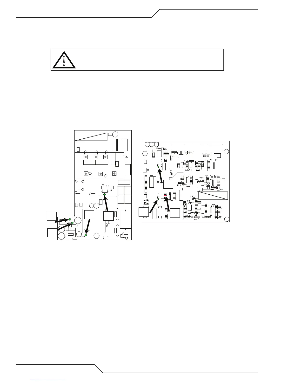
2. Bias Supply checks at Power On
In approximately 4 seconds expect Bias board 4 LEDs, +15V PRI (D327); +15V (D336); -15V (D340); +24V (D337),
to light on the Bias board and one LED, D101, on the rear of the Control board followed by a second Control
board LED, D135, that blinks slowly. If all expected Bias and control board LEDs light skip to step #3.
GRN/YEL
ORANGE
VIOLET
BLACK
ORANGE
BLACK
CHASSIS
GND
(3Ø ONLY)
+15V PRI
+24V
-15V
+15V
3Ø
1Ø
AC1
AC2
AC3
GND PRI
BRIDGE+
TP21
TP8 TP23
TP22
TP4
ACINSEN
HI LINE
BUS CHK
LO LINE15 UV
+
C303
D301
D303
HS300 HS301
C302
+
C300
C307
+
C306
+
C304
+
C301
D304
D306
D305
D307
1
J305
1
J304
46
13
J303
K300
MOV300 MOV301 MOV302
1
J302
Q301Q300
R300
R303
R301
R302
T300
1
U300
1
U301
+
C305
HS302
1
J301
D300
1
2
5
6
J300
T301
D302
MOV306
MOV304
MOV305
MOV303
E300
GND
15V
APPLY RTV TO COMPLETELY COVER PINS IF NEEDED
GREEN
YELLOW
ORANGE
RED
BROWN
BLACK
C
C
C
C
C
GND
OPEN
START
ISP
PROG
NORM
1
1
TP100_
TP1_
R268
R267
R265
D135
R175
C139
C168
C136
C138
+
C115
C171
+
C117
C142
C135
C151
C134
C146
C153
C161
C112
C160
C172
C130
C129
C173
C167
C158
C163
C164
C165
C169
C170
C143
C152
C150
C149
C109C107
C166
C156
C162
C159
C157
C120
+
C116
C124
C132
C118
C125
C122
C121
C126
C119
C123
C148
C108
C104
C106
C110
C127
C128
C144
C140
C141
C145
C147
C154
C155
D148
D169
D147
D101
D177
D146
D144
D152
D151
D165
D154
D167
D173
D174
D168
D170
D163
D164
D157
D166
D175
D172
D176
D171
D153
D155
D156
D149
D150
D161
D159
D162
D158
1
J102
1
J101
L102
1
502
49
J100
1
J103
R242
R231
R233
R253
R161
R167
R238
R162
R158
R266
R256
R187
R153
R192
R180
R154
R145
R208
R193
R185
R209
R206
R183
R205
R228
R203
R197
R230
R227
R223
R264
R144
R147
R138
R240
R152
R243
R261
R255
R150
R139
R211
R177
R176
R226
R224
R218
R236
R220
R234
R251
R263
R229
R232
R258
R259
R241
R260
R262
R254
R252
R182
R181
R178
R189
R196
R210
R170
R173
R199
R202
R190
R194
R169
R113
R112
R107
R108
R109
R257
R155
R160
R163
R111
R237
R215
R239
R110
R216
R235
R221
R219
R222
R217
R122
R121
R140
R137
R213
R149
R143
R146
R151
R165
R148
R135
R131
R120
R123
R132
R126
R125
R124
R130R129
R127
R133
R128
R136
R134
R168
R166
R201
R204
R250
R249
R248
R245
R244
R164
R214
R171
R198
R172
R184
R188
R207
R212
R174
R200
R247
R246
R179
R195
R186
R191
1
U113
1
U111
1
U106
1
33
U102
U101
1
U107
1
U114
1
U112
1
U104
1
U108
1
U110
1
U109
Y100
C174
D178
D179
Art # A-13303
+15V
+24V
-15V
+15V
PRI
D135
D159
D101
a. If all Bias LEDS light but either of the Control & Display LEDs do not, skip to step #2e.
b. If none of the Bias LEDs light test for input power.
i. Verify the unit is plugged in and the outlet has power. Verify the rear panel circuit breaker (CB1) is
turned on. Test for AC input voltage between the 2 AC terminals of the D300 bridge rectifier if single
phase or all 3 AC terminals if 3 phase.
ii. Measure for DC voltage between the GND PRI (-) and BRIDGE+ terminals. DC Voltage should be
approximately the same as the phase to phase AC voltage.
iii. Now measure from GND PRI (-) to J305-3. The voltage may be as high as 750VDC. The Bias board
should operate at any voltage over 230 VDC. If not replace the Bias board.
c. If some of the Bias LEDs don’t light but at least one does, shut off power to the unit. Allow at least one
minute for capacitor bleed down then disconnect J302 & 303 on the Bias board. Turn power back on. If
all the LEDs still don’t light replace the Bias board.