CUTMASTER 60i
Manual 0-5475 SERVICE
5-21
d. If all the LEDS now light there is a short at the other end of either the J302 or J303 harness. Plug them in
one at a time to determine which one is loading the Bias down.
i. J302 goes to the PFC board at J800 and the Inverter board at J610. Disconnect each of these in turn
and replace the board that was loading it down.
ii. J303 goes to the Inverter board. If J303 is loading the Bias down, disconnect the ribbon cables at J600,
the fan at J608, the current transducer at J601. If the unit is equipped with an Automation Interface
board disconnect its harness at J609.
iia. Now if any of the Bias supply LEDs are being loaded down replace the Inverter board.
Otherwise reconnect the removed connectors one at a time to find what component is causing
the problem and replace that.
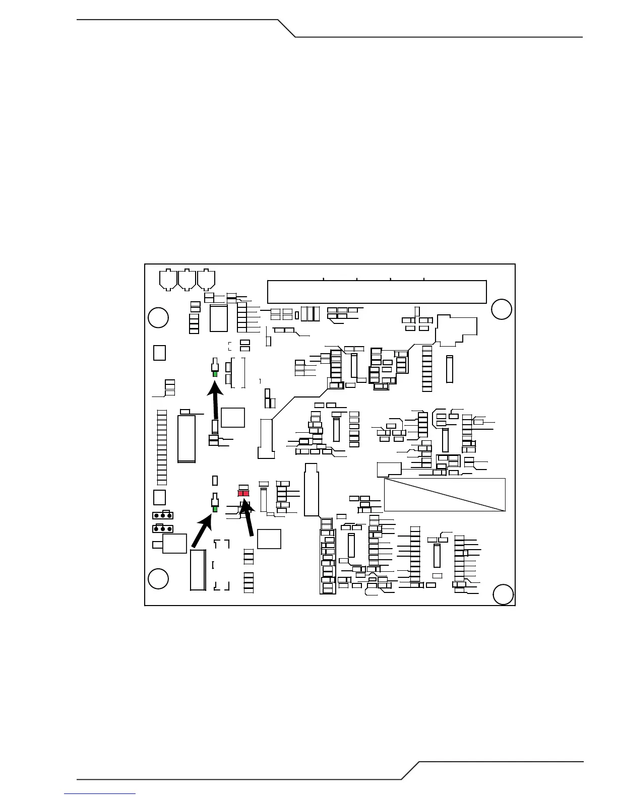
e. Control board LED D101 illuminated indicates +15V is supplied to the board and the blinking “Heartbeat”
LED, D135, indicates the microprocessor is operating.
f. If D101 does not light it may indicate +15V not getting to the board. If the display, front of the board, is
dark, measure for +15V at TP100_15V relative to TP1_GND on the back side of the Control & Display
board If +15V is present it may be only the LED is defective.
GND
15V
APPLY RTV TO COMPLETELY COVER PINS IF NEEDED
GREEN
YELLOW
ORANGE
RED
BROWN
BLACK
C
C
C
C
C
GND
OPEN
START
ISP
PROG
NORM
1
1
TP100_
TP1_
R268
R267
R265
D135
R175
C139
C168
C136
C138
+
C115
C171
+
C117
C142
C135
C151
C134
C146
C153
C161
C112
C160
C172
C130
C129
C173
C167
C158
C163
C164
C165
C169
C170
C143
C152
C150
C149
C109C107
C166
C156
C162
C159
C157
C120
+
C116
C124
C132
C118
C125
C122
C121
C126
C119
C123
C148
C108
C104
C106
C110
C127
C128
C144
C140
C141
C145
C147
C154
C155
D148
D169
D147
D101
D177
D146
D144
D152
D151
D165
D154
D167
D173
D174
D168
D170
D163
D164
D157
D166
D175
D172
D176
D171
D153
D155
D156
D149
D150
D161
D159
D162
D158
1
J102
1
J101
L102
1
502
49
J100
1
J103
R242
R231
R233
R253
R161
R167
R238
R162
R158
R266
R256
R187
R153
R192
R180
R154
R145
R208
R193
R185
R209
R206
R183
R205
R228
R203
R197
R230
R227
R223
R264
R144
R147
R138
R240
R152
R243
R261
R255
R150
R139
R211
R177
R176
R226
R224
R218
R236
R220
R234
R251
R263
R229
R232
R258
R259
R241
R260
R262
R254
R252
R182
R181
R178
R189
R196
R210
R170
R173
R199
R202
R190
R194
R169
R113
R112
R107
R108
R109
R257
R155
R160
R163
R111
R237
R215
R239
R110
R216
R235
R221
R219
R222
R217
R122
R121
R140
R137
R213
R149
R143
R146
R151
R165
R148
R135
R131
R120
R123
R132
R126
R125
R124
R130R129
R127
R133
R128
R136
R134
R168
R166
R201
R204
R250
R249
R248
R245
R244
R164
R214
R171
R198
R172
R184
R188
R207
R212
R174
R200
R247
R246
R179
R195
R186
R191
1
U113
1
U111
1
U106
1
33
U102
U101
1
U107
1
U114
1
U112
1
U104
1
U108
1
U110
1
U109
Y100
C174
D178
D179
D159
D101
D135
i. +15V comes over the ribbon cable from the Inverter board. If no +15V and no display on the Control
board remove the ribbon cable from the Control & Display board and measure for +15V on the end
of the disconnected ribbon cable at pins 5 & 6 with ground on any of pins 2, 4, 8, or 10 of the ribbon
cable connector. You will need a small probe, no more than 0.025” dia. A paper clip is too big and can
damage the connector.