2-46
C2330
C2331
C2332
C2333
Assembly (cont’d)
DRIVE MOTOR 2.12
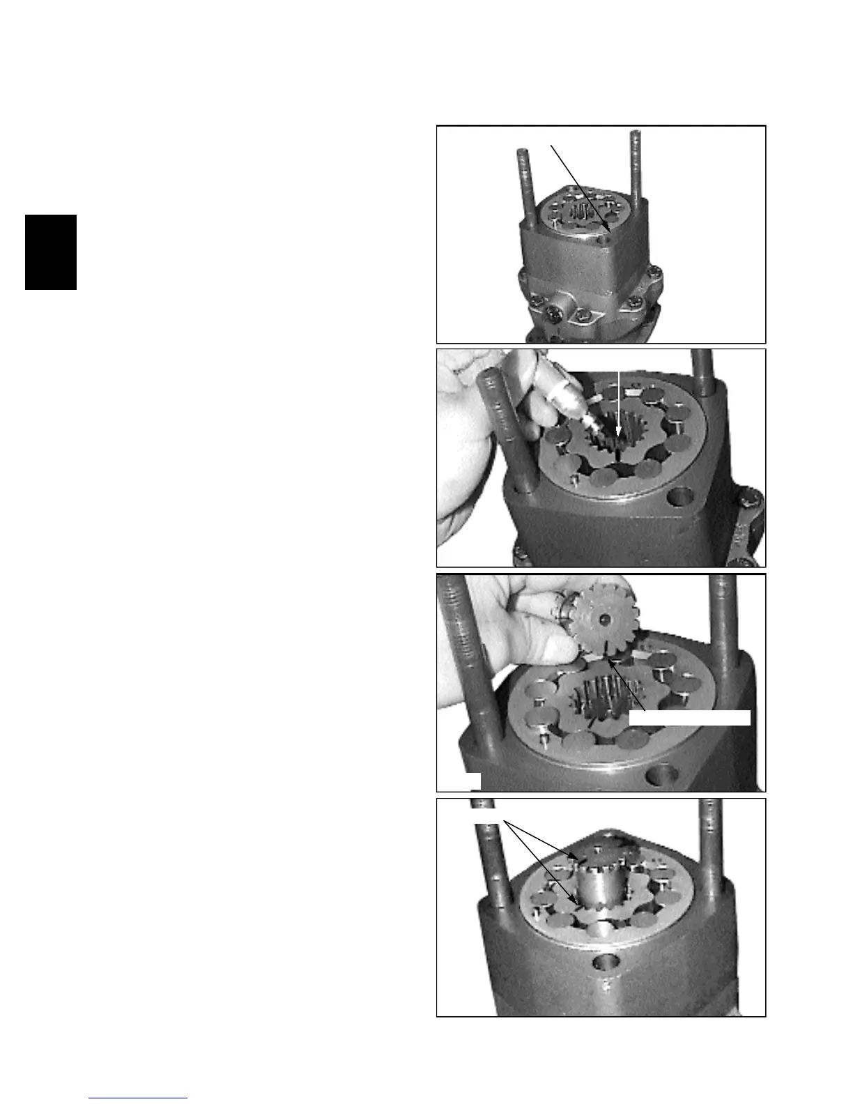
The following procedures must be followed closely
for proper motor rotation.
15 Mark the gearwheel set rotor at the point where the
top of a spline tooth is opposite the bottom of a tooth in
the external rotor teeth. (fig. C2331).
17 Install the valve drive lining up the marks on the
valve drive to the gearwheel set. (fig. C2333).
16 Mark the bottom of a spline tooth on the valve drive.
(fig. C2332).
14 Install the geroler section the housing. (fig. C2330)
Place a hand under the geroler to prevent the pieces from
falling out.
Mark the gearwheel
Mark the valve drive
Line up the marks
Install geroler section