1-14
Remove the hydraulic control valve as outlined in the
removal section, page 1-7. Ensure all openings are
plugged to prevent solvents and dirt from contaminating
the control valve assembly. Before disassembling the
hydraulic control valve, clean the body with a suitable
solvent and dry with compressed air.
Refer to diagram C1079, pg. 1-11, to assist in the
disassembly of the control valve.
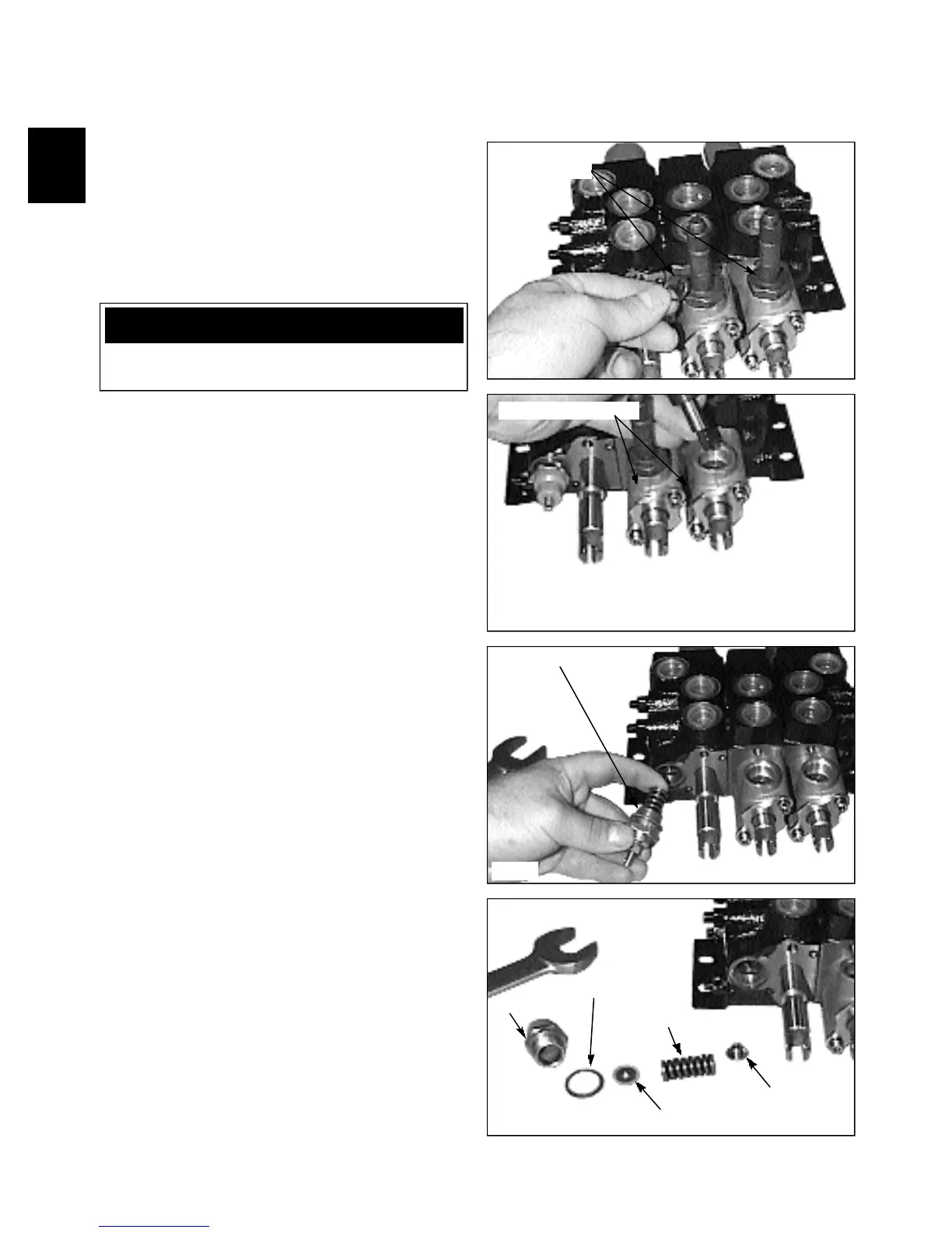
1 Remove the solenoid coils and O-ring seals. (fig.
C2368).
2 Remove the locking pin assembly from the adapter
block. (fig. C2369)
3 Remove the pressure relief valve. (fig. C2370) Tip
the valve down slightly to ensure the valve poppet comes
out with the spring.
Note: Figure C2371 shows an exploded view of the
relief valve system.
CONTROL VALVE 1.3
Disassembly / Repair
WARNING
To avoid eye injury, use safety goggles when clean -
ing with compressed air.
C2368
C2369
C2370
C2371
O-ring seals
Locking pin assembly
Relief valve assembly
Cap
Sealing washer
Spring washer
Spring
Valve poppet