1-15
CONTROL VALVE 1.3
C2372
C2373
C2374
C2375
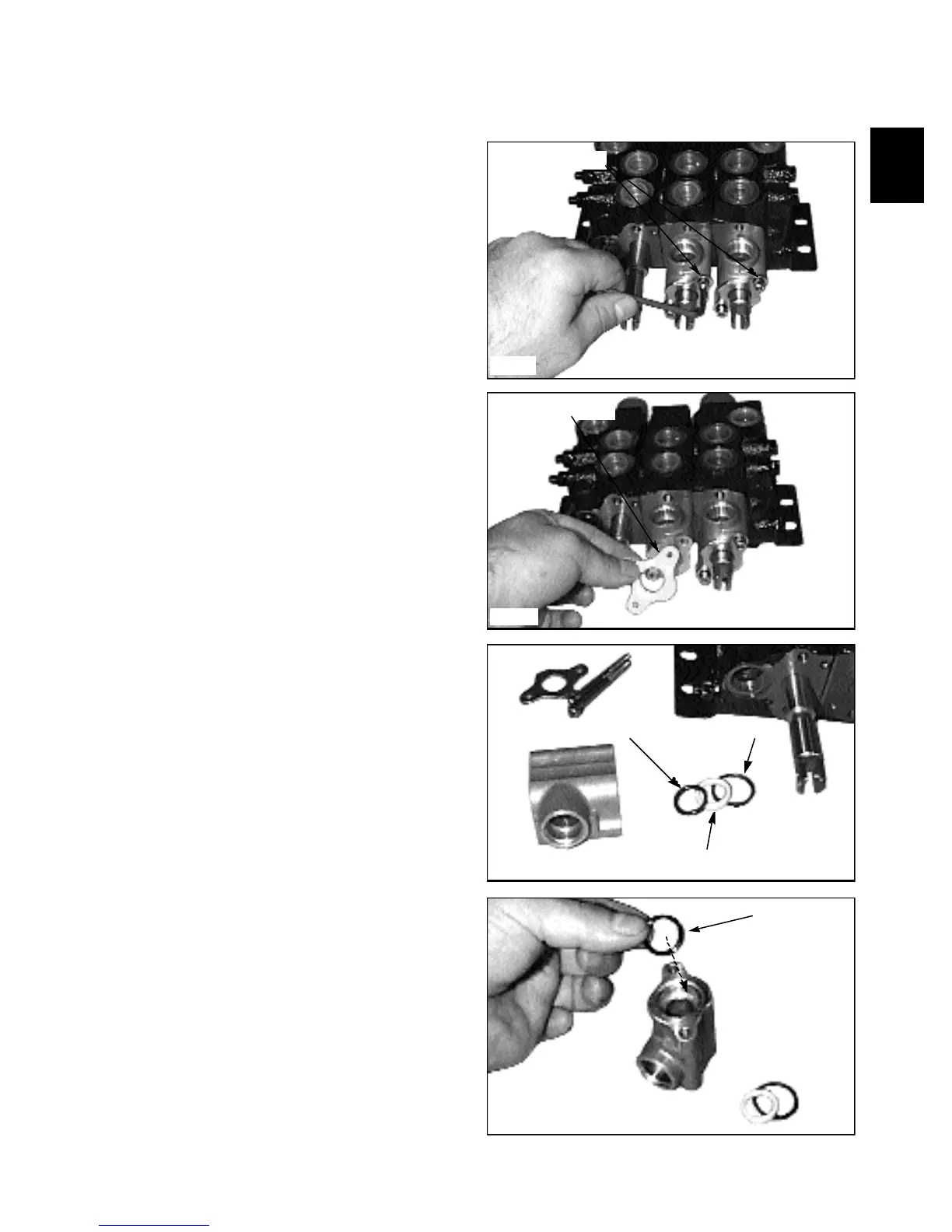
4 Remove the screws retaining the lock adapters to the
control valve assembly. (fig. C2372).
5 Remove the plate and adapter from the control valve
and spool. (fig. C2373, C2374)
Disassembly / Repair (cont’d)
Remove screws
Scraper seal plate
Spool O-ring
Spool O-ring
O-ring shim
Section O-ring
6 Remove the O-ring seals and seal shim. (fig. C2374).
Discard the seals and replace with new.
7 Clean the lock adapter with solvent and inspect the
inside of the lock adapter for excessive wear such as
gouging or chipping. Replace with new if worn.
8 Lubricate a new spool O-ring with system oil and
install to the lock adapter. (fig. C2375)