Portable Connector End Face Geometry Interferometer Chapter 12: Appendix
Rev B, April 16, 2019 Page 62
4. APC Angle (°) – Displays the angle of polish calculated using the calibrated Y Offset. NOTE: Only 8° angle
polished connectors can be measured with the CC6000 and CC6000 Software. Angle measurements are
only displayed if APC is selected as the Connector type in the Setup Tab.
5. Key Error (°) – Displays the keying error of the connector endface calculated using the calibrated X Offset.
NOTE: Key error measurements are only displayed if APC is selected as the Connector type in the Setup
Tab.
12.2. Interferometry Basics
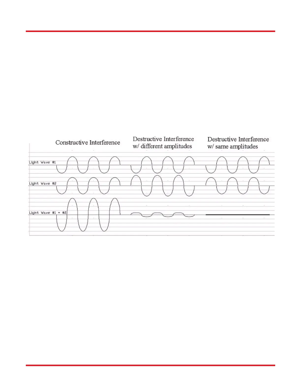
Light wave interference occurs when two or more waves of the same frequency or wavelength combine to form a
single wave whose amplitude is the sum of the amplitudes of the combined waves. Constructive and Destructive
interference is the most striking examples of light wave interference. Constructive interference occurs when the light
waves are completely in phase with each other (the peak of one wave coincides with the peak of the other wave).
Destructive interference occurs when the light waves are completely out of phase with each other (the peak of one
wave coincides with the trough of the other wave). Refer to figure below for an illustration of Constructive and
Destructive interference.
Interferometers can produce images and data to sub micron accuracy using the principle of wave interference.
Interferometers use a single coherent light source. In order to produce two separate light waves for interference to
occur, a partially reflective beam splitter is used. As the light hits the beam splitter, one wave front is transmitted
through the beam splitter, though an objective lens, and to the object being examined. The other light wave reflects
off of the beam splitter onto a stationary reference mirror. After both light waves are reflected off of the surfaces
(the surface of the object being examined and the reference mirror), the waves combine to produce constructive
and destructive interference waves, also known as light and dark fringes respectively. Each dark fringe identifies a
specific height on the surface of the object being examined. Typically, two adjacent dark fringes have a height
difference of 1/2 a wavelength of the light being used and can thus show a surface contour of the connector end
face, very similar to the concept of Contour maps which are used to show the different elevations of a land surface.