Portable Connector End Face Geometry Interferometer Chapter 12: Appendix
Rev B, April 16, 2019 Page 58
Chapter 12 Appendix
12.1. Data Interpretation
The CC6000 and the CC6000 Software uses Tilted Phase Data Collection. Using Tilt Phase technology, the
connector is held at a constant tilted angle for measurements, which allows for fringes to cross the ferrule and fiber
surfaces. With the fringe pattern generated, all information needed for data calculation is displayed in the Live
Image. Since the connector is held at a slight angle, the relationship between the fiber center and the apex offset
is not true to scale, therefore it is imperative to conduct calibration procedures prior to connector measurements.
During the calibration procedures, the software automatically detects the X and Y correction factors that will give
accurate and repeatable end face measurements.
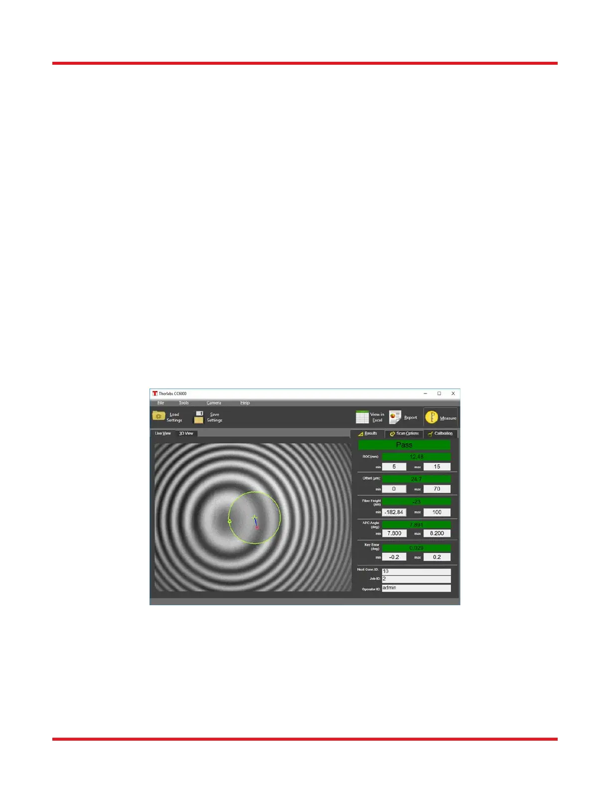
At the completion of a successful scan, the scan details on the live image and the quantitative measurements of
the endface parameters are displayed: (NOTE: The Results tab may be different from what is shown in the screen
capture below depending on the parameters selected in the Scan Options/ Scan Settings subtab. Illustrated below
is an APC measurement with Display Mode set to “Value”).
1. Radius of Curvature (mm)
2. Offset (µm)
3. Fiber Height (nm)
4. APC Angle (°)
5. Key Error (°)