Portable Connector Chapter 10: Measurement
Page 53 TTN169162-D02
Chapter 10 Measurement
The CC6000 is a fully automated, non-contact, interferometric microscope system designed to measure the end
face geometry of fiber optic single fiber connectors. The system measures the radius of curvature, eccentricity of
polish (also known as apex offset), and the fiber height for fiber optic connectors.
This section provides detailed procedures, explanations, and pictures of the measuring process to familiarize our
customers of what to expect from the CC6000 system and CC6000 software.
1. Calibration procedures to level the mount prior to taking measurements (see page 46). Calibrations should
be conducted in Mode 1 (Ceramic Ferrule Material Setting).
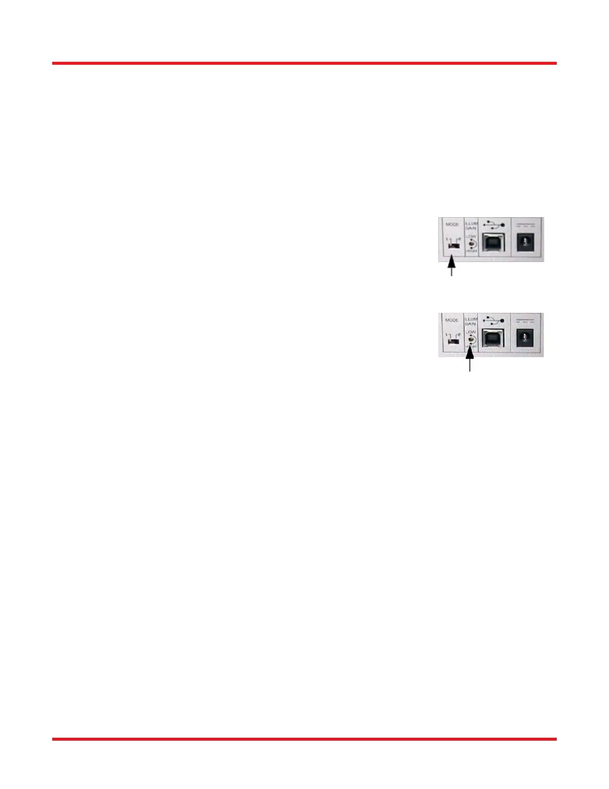
2. Adjust Ferrule Material Settings.
a. If measuring a ceramic connector, switch to Mode 1.
b. If measuring a metal connector, switch to Mode 2.
3. Adjust Illumination
a. Select BAT under Camera Menu to adjust the illumination, brightness.
Click start on the BAT dialog to see the Brightness Status. If Status
reads “No Change” close the dialog.
b. If the Status reads INCREASE or DECRESE, turn the Illum to Low to
High until the Brightness status reads “No Change” (see page 29).
4. Modify/Load Set-Up Parameters [Scan Settings in Scan Options tab (see page 41)] to control the data
during the measurement process according to the connector being tested.
5. Modify Option Parameters [Save/Print Settings in Scan Options tab (see page 45)] to control how the
data is organized after the measurement process is completed. The data can be controlled to automatically
save data to a specific group name and data path, and/or auto print reports of data measurement.
6. Clean Connector Properly to assure accurate measurements during the scanning process. It is important
to clean any residue from polishing that may have collected on the ferrule/fiber.
7. Insert the Connector Properly into the Mount to assure accurate measurements during the scanning
process.
8. Adjust Focus Knob - Adjust the focus knob to optimize the fringe contrast over the entire surface.
9. Measure the Connector - Press Measure button in the Results Tab.
At the completion of a scan, a beep is sounded to indicate the completion of frame capturing from the camera. Once
the beep has sounded, the connector under test can be removed from the mount and a new connector can be
inserted in preparation for the next scan. Results will be displayed when data analysis is completed.