Portable Connector End Face Geometry Interferometer Chapter 9: Control Tabs
Rev B, April 16, 2019 Page 52
STEP 6
• As instructed on the Leveling Connector
Calibration dialog, rotate the connector in the
mount by approximately 45 degrees between
each of 8 total measurements, clicking the
“Step <>” button after rotating. Be sure to
keep the mount locked (or relock after rotation
if unable to rotate while locked). Also, refocus
between steps if needed.
• Make sure not to cause any vibration during
the scanning process.
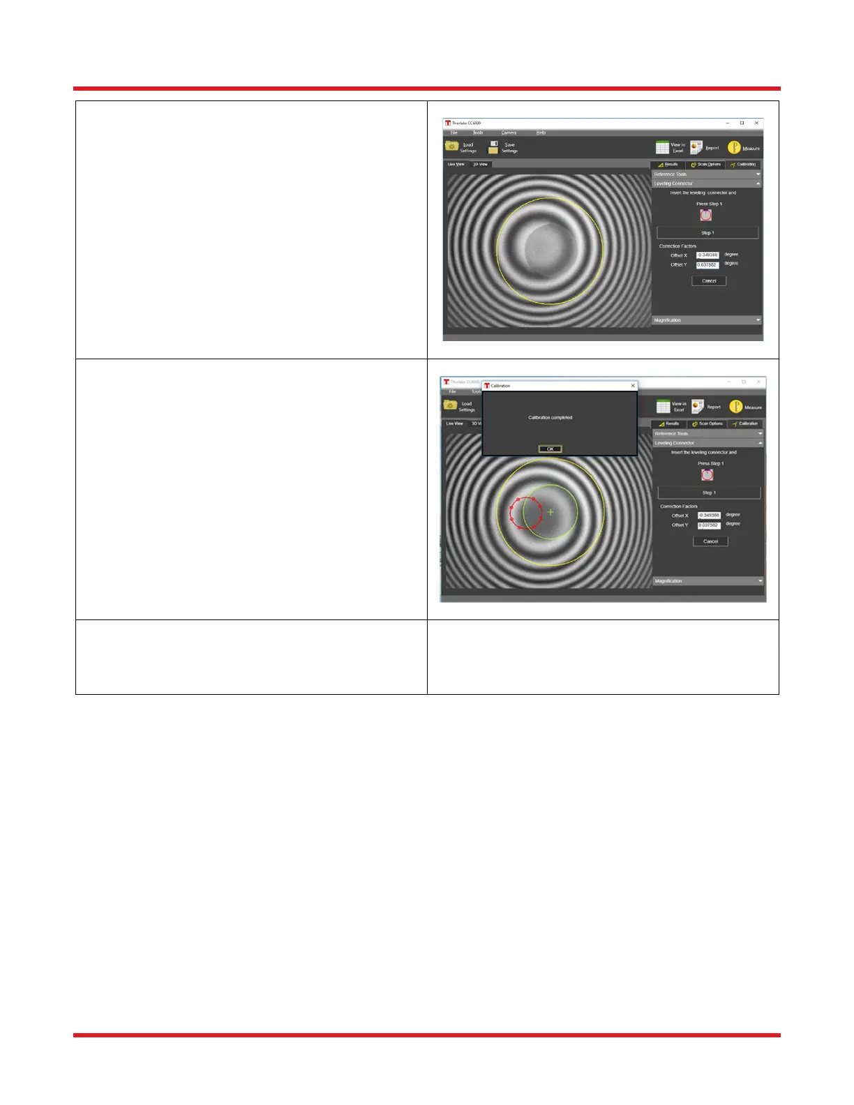
STEP 7
• After the calibration is complete, the
calculated apex-offset correction factors are
displayed in the area marked by the box in the
figure shown. A “calibration complete”
message will appear, and the Live View will
show a red circle fit to the set of 8 apex spots
detected for each step.
o NOTE: In the Live View, after completion,
the green circle should match up perfectly
with the outer edge of the Reference Tool
fiber hole. If it does not, please repeat the
Offset Calibration.
STEP 8
• Proceed to Connector Measurement
procedure.