Portable Connector End Face Geometry Interferometer Chapter 10: Measurement
Rev B, April 16, 2019 Page 54
10.1. Connector Measurement Procedure
STEP 1
Obtain the following:
• Computer and Monitor powered up with CC6000 software running.
• CC6000 Microscope
• Mount
o PC - Specific to the ferrule size of the connectors being measured.
OR
o APC - Specific to the connector type (i.e. FC, ST, or LC)
• Mount screws
• Alcohol & Lint free wipes or the supplied connector cleaner
• Connectors to be analyzed.
NOTE: This procedure can also be used for customer-specific mounts.
STEP 2
• Calibrate the mount:
o Use Reference Tool (or Leveling Connector) Calibration Procedure for PC mounts
o Use Reference Tool Calibration Procedure for APC mounts
• Set rear panel Mode switch according to Ferrule Material.
o Mode 1 for Ceramic ferrule.
o Mode 2 for Metal ferrule.
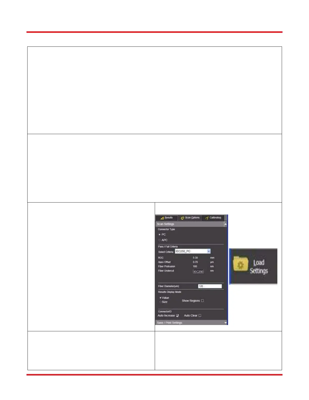
STEP 3
• Choose Scan Configuration
o Two ways to do this:
• Click Scan Options/Scan Settings subtab
and select options appropriate to the
connector being measured and mount
being used:
• Load a previously saved Settings
Configuration using the toolbar Load
Settings tool.
STEP 4
• Also under the Scan Options tab, both the Scan
Settings & Save-Print subtabs should be
configured as desired to control how the data is
displayed and saved.