Portable Connector End Face Geometry Interferometer Chapter 9: Control Tabs
Rev B, April 16, 2019 Page 48
9.4. Reference Tool Calibration
STEP 1
Obtain the following:
• PC or APC Reference Tool (2.50 mm or 1.25 mm depending on the mount being used)*
• Computer and Monitor powered up with CC6000 software running.
• CC6000 Microscope
• 2.50 mm or 1.25 mm Locking V groove Mount specific to the connectors that will be analyzed and
mount screws*
• Alcohol & Lint free wipes or the supplied connector cleaner
*This procedure can also be used for customer-specific mounts/leveling tools.
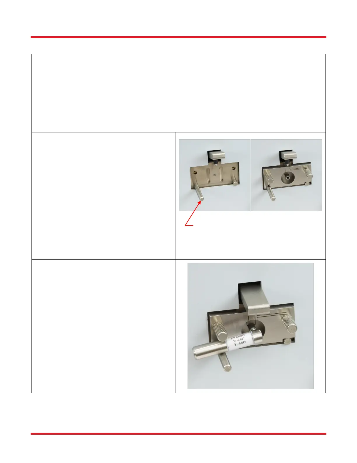
STEP 2
If mount is not attached to the interferometer:
• Make sure the locking lever is in the
unlocked position by pushing the lever up.
(Picture A)
• Use compressed air to blow dirt/dust off the
surface of the mount area. (DO NOT use
compressed air when the mount is attached
to the microscope.)
• Place the mount onto the interferometer so
the groove on the bottom of the mount rests
on the locating pin on the left and the cutout
rests on the pin on the right. (Picture A)
• Secure the mount into place using the two
thumb screws.(Picture B)
STEP 3
• Make sure the mount is in the unlocked
position by pushing the locking lever
upwards.
• Clean the Reference Tool and insert it into
the mount so that it is inserted all the way
into the mount AND that the lever is resting
on the locating pin as shown.
• Lock into place by pushing the locking lever
down.
• Look at the Live Image and make sure all
dust is cleaned off the reference tool. Both on
the surface and inside of the hole of the
connector. The edges of the ID of the ferrule
should be fairly smooth.