Portable Connector End Face Geometry Interferometer Chapter 9: Control Tabs
Rev B, April 16, 2019 Page 50
STEP 7
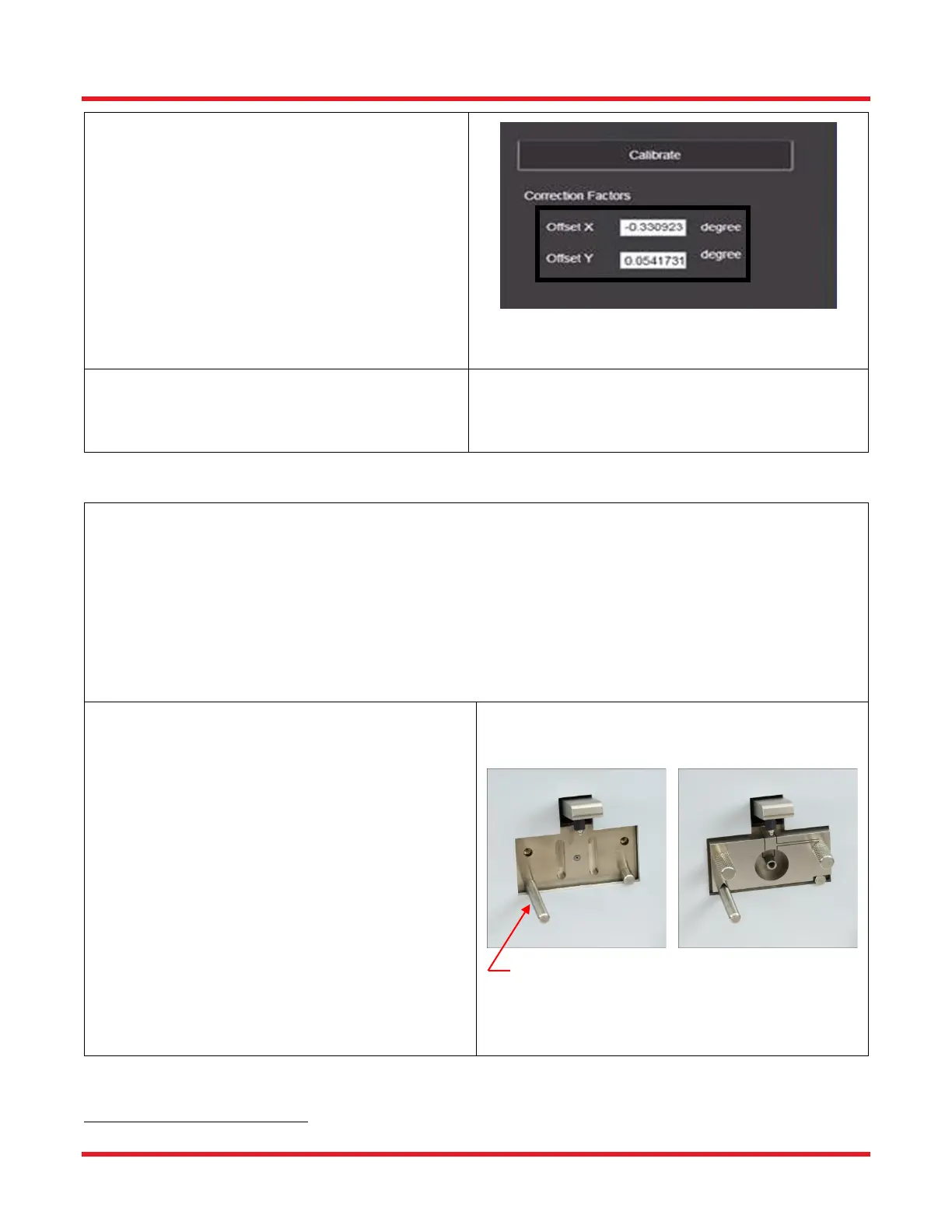
• After the calibration is complete, the
calculated apex-offset correction factors are
displayed in the area marked by the box in
the figure shown. A “calibration complete”
message will also appear.
• NOTE: In the Live View, after completion, the
green circle should match up perfectly with
the outer edge of the Reference Tool fiber
hole. If it does not, please repeat the
Reference Tool Calibration.
STEP 8
• Proceed to Connector Measurement
procedure.
9.5. Leveling Connector Calibration
STEP 1
Obtain the following:
• Thorlabs Leveling Connector (2.50 mm or 1.25 mm depending on the mount being used)*
• Computer and Monitor powered up with CC6000 software running.
• CC6000 Microscope
• 2.50 mm or 1.25 mm Locking V groove Mount specific to the connectors that will be analyzed and
mount screws*
• Alcohol & Lint free wipes or the supplied connector cleaner
*This procedure can also be used for customer-specific mounts/leveling tools.
STEP 2
• If mount is not attached to the interferometer:
o Make sure the locking lever is in the
unlocked position by pushing the lever up.
(Picture A)
o Use compressed air to blow dirt/dust off the
surface of the mount area. (DO NOT use
compressed air when the mount is
attached to the microscope.)
o Place the mount onto the interferometer so
the groove on the bottom of the mount
rests on the locating pin on the left and the
cutout rests on the pin on the right. (Picture
A)
o Secure the mount into place using the two
thumb screws.(Picture B)
Please contact techsupport@thorlabs.com for more information on these custom leveling connectors.