Portable Connector Chapter 12: Appendix
Page 59 TTN169162-D02
1. Radius of Curvature (mm) – Displays the radius of curvature (ROC) determined by the curvature of the
fringes located within the fiber diameter.
2. Offset (µm) – Displays the apex offset. The apex offset is defined as the distance from the vertex (high
point) of the ferrule sphere to the center of the fiber. Interferometry, because of its three dimensional
contours, visually shows the vertex of the apex offset as the center of the circular fringes that define the
sphere.
Using Tilted Phase Data Collection, the relationship between the fiber center and the apex offset is not true
to scale with the center of rotation of the apex offset no longer the same as the fiber center. The Live Image,
therefore shows the Apex Offset much further away from the fiber center, and calibration procedures must
be conducted to compensate for the connector being held at a constant angle. At successful completion of
a measurement, the calibrated Apex Offset measurement is shown as a graphics overlay onto the Live
View. This, then, illustrates the true-to-scale relationship between the fiber center and the calibrated apex
offset.
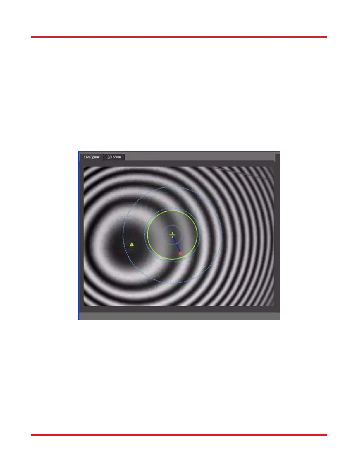
The Live View overlaid graphics can be interpreted as follows:
1. Measured Results:
a. Measured fiber center (green cross hair)
b. Fiber diameter (large green circle
c. Measured apex location (small green triangle)
2. Calibrated Results
a. Calibrated apex offset (small red circle)
b. True Distance between the measured fiber center and Calibrated Apex Offset (blue
line)
3. Measurement Regions (when “Show Regions” option is selected in Scan Settings subtab)
a. Innermost of three concentric blue circles = Averaging Diameter
b. Middle of three concentric blue circles = Extraction Diameter
c. Outermost of three concentric blue circles = Fitting Diameter
 Loading...


