© 2019 Thorlabs GmbH
5 Operating Instruction
36
5.2.6 Extinction Ratio Measurement
The PAX1000 allows the measurement of the Extinction Ratio (ER) of polarization maintaining
fibers (PMF). Please see the section Extinction Ratio Measurement on PM Fibers for theory
and basics.
Measurement Setup
For correct ER measurements, a linearly polarized light source is mandatory. This can be a pig-
tailed laser diode with a PMF output fiber, or a free space laser combined with a fiber coupler
and a Thorlabs Fiber-To-Fiber U-Bench or a manual fiber polarization controller.
The DOP (degree of polarization) of the light source should be as close to 100% as possible.
Also, the operating wavelength must be well known, and the optical power must not exceed the
specification of the PAX1000.
It is important to couple the linearly polarized light parallel to the slow axis of the fiber under
test.
The output of the fiber under test is connected to the PAX1000 using the supplied fiber collim-
ator with the SM1 adapter.
Note
The F240FC-x collimator is designed for FC/PC connectors. If your fiber under test has an
angled connector (FC/APC), please purchase a Thorlabs F240APC-x collimator.
"x" stands for the operating wavelength range of the anti-reflective coating and must match with
your PAX1000 and the operating wavelength of your setup.
The fiber under test must be dynamically stressed while the ER measurement is performed.
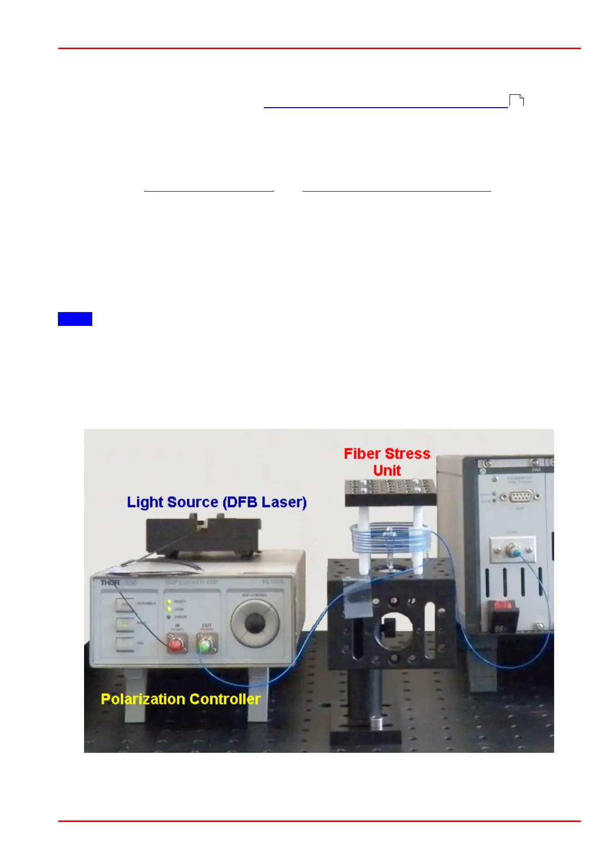
Below, an example of an ER Measurement Setup is shown:
The optical test signal is generated by a DFB laser diode. Its output is connected to a Thorlabs
GmbH PL100S deterministic polarization controller. The PMF under test (fiber with blue jacket)
73
 Loading...


