© 2019 Thorlabs GmbH29
PAX1000
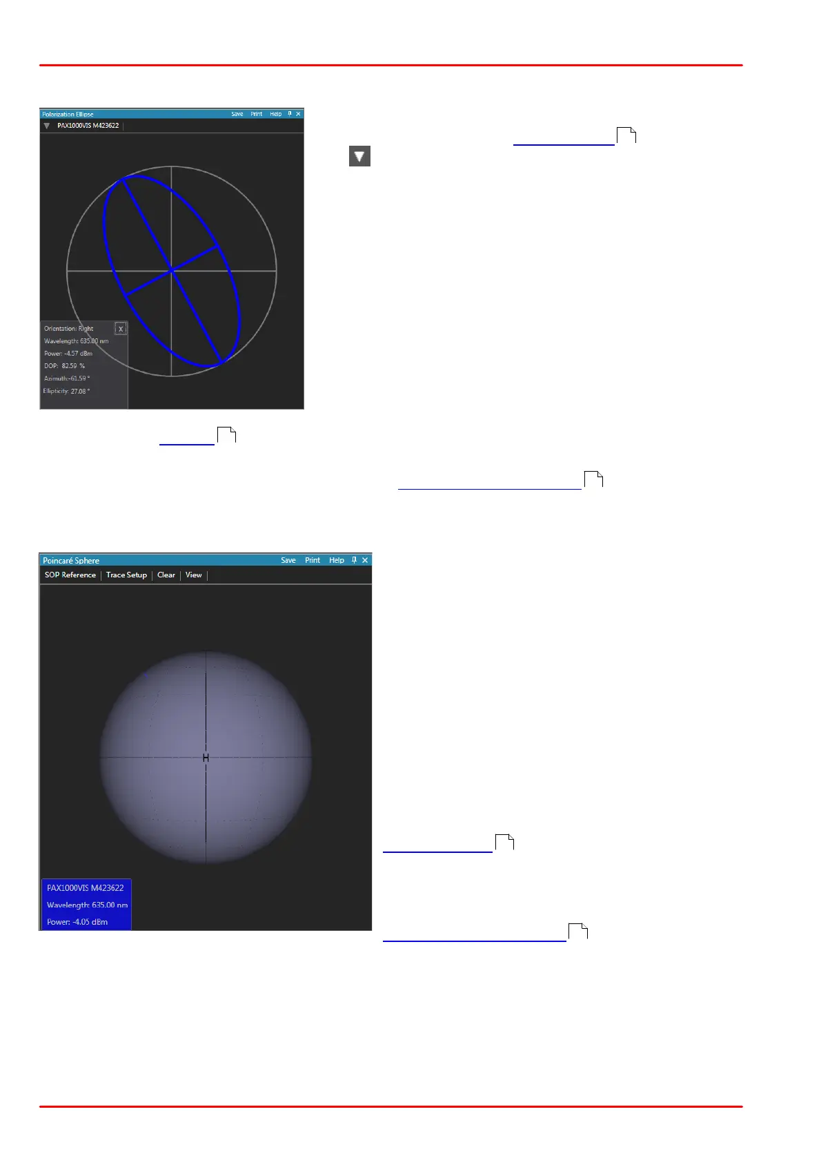
5.2.2 Polarization Ellipse
In this view, the polarization ellipse is displayed. The el-
lipse color depends on the device setting .
The icon in the left upper corner allows to select one
of the connected polarimeters for display.
Below the ellipse, a box with numerical parameters is
shown. The first four parameters
- orientation (handedness)
- wavelength
- total power
- DOP (degree of polarization)
are shown at any time.
By clicking to the grey area, the display of the additional
parameters can be changed:
- azimuth and ellipticity, or
- power split ratio and phase difference, or
- the 3 normalized Stokes vectors s1, s2 and s3.
Please see the Tutorial for detailed information on these parameters. The numerical para-
meters can be hidden (X); then the small i icon will restore them.
For functions in the blue header line, please see Functions in View panels .
5.2.3 Poincaré Sphere
The default view of the Poincaré sphere is
shown in the screenshot.
Viewing options
· Click the colored box to show the current
SOP in front. If you have more than one
PAX1000 connected, the click shows the current
SOP of the selected device.
· Hold the left mouse button and drag to rotate
the sphere.
· Scroll the mouse wheel or press + (-) to zoom
the view.
· To move the sphere, press A (left), D (right),
W (up) or S (down).
· Press Ctrl and left mouse button to create a
SOP reference .
· Press Ctrl, hold down right mouse button and
drag to create a circular marker on the sphere.
For functions in the blue header line, please see
Functions in View panels .
Menu SOP References
A SOP reference is a certain, user-configurable state of polarization that can be used as a ref-
erence point. In combination with the dSOP parameter, this allows to measure the polarization
shift of the actual state of polarization from the reference point.
Up to 20 reference SOPs can be defined.
21
53
16
29
16
 Loading...


