© 2019 Thorlabs GmbH73
PAX1000
8.4 Extinction Ratio Measurement on PM Fibers
8.4.1 Definition
A Polarization Maintaining Fiber (PMF) is only effective if linearly polarized light is launched par-
allel to the fast or slow axis.
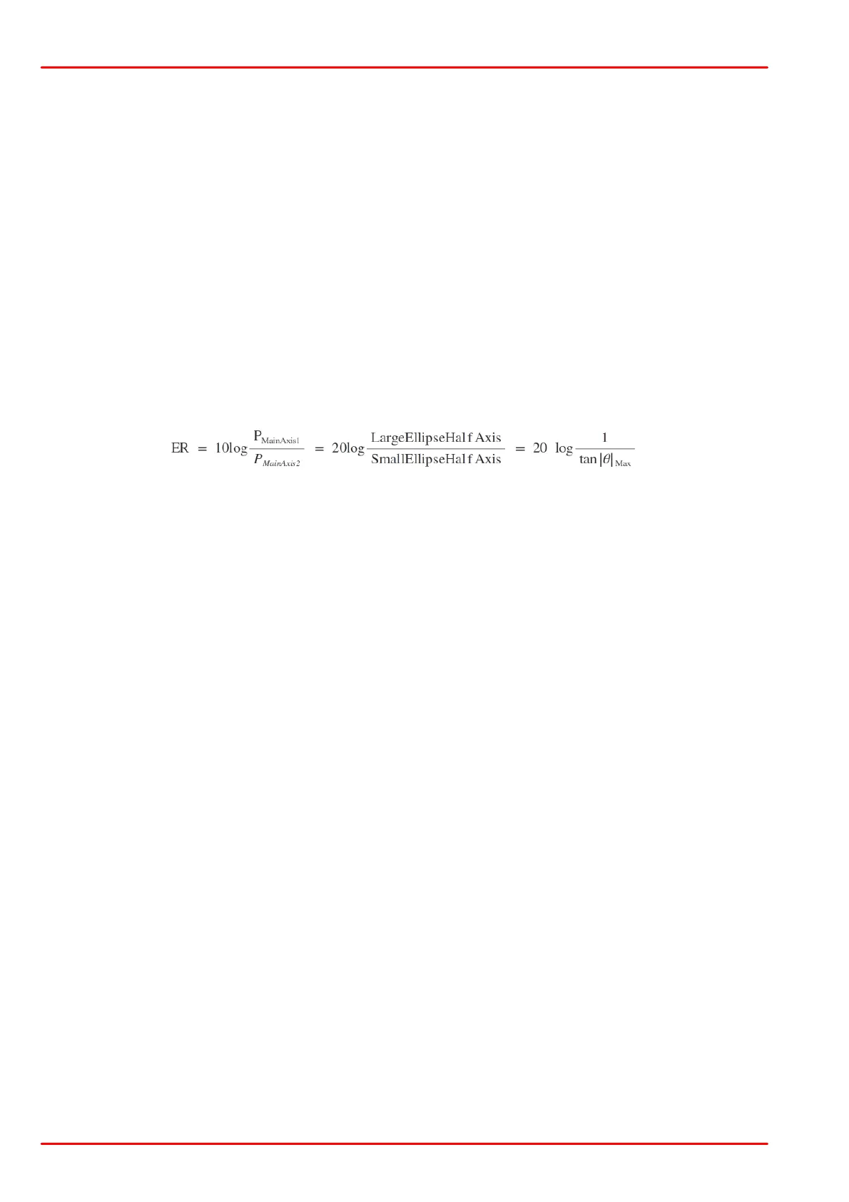
The ratio of the power in the fast and slow axis (in dB), the so-called Extinction Ratio (ER), is
a measure of the quality of this coupling.
The extinction ratio is measured at the output of the PMF. First the polarization state is de-
scribed using the polarization ellipse, which is the 2D curve traced out by the rotating polariza-
tion vector. The length of the major and minor axes of the ellipse are proportional to the amount
of optical power coupled into the two axes of the PMF. For example, if all power is coupled into
one axis, the ellipse will be a line, and if the power is evenly split between the two axes the el-
lipse will be a circle. As the instantaneous position of the polarization vector on the ellipse is a
function of the distance from the output of the PMF, the measurement plane should be trans-
lated back and forth to determine the maximum and minimum values of optical power, P
MainAxis1
and P
MainAxis2
, respectively.
Given a linear polarization state launched optimally into either the fast or slow axis, the ER ex-
presses the ability of the PMF to maintain that state by suppressing cross-coupling that would
transfer power to the orthogonal polarization state. The ER is therefor a crosstalk specification.
If the ER is poor then either the PMF has a poor polarization preserving capability (or enhanced
mode coupling) or the alignment into the PMF is not optimal.
A PMF preserves the linear polarization state of the input only if the polarization state at the in-
put is linearly polarized and perfectly aligned with one of the principal PM axes (polarization ei-
genstates).
If linearly polarized light is coupled into both the fast and the slow axes of the PMF, the two
components will propagate independently of one another through the fiber. For this discussion
it can be assumed that there is no cross-coupling between them. Due to the PMF's birefrin-
gence, the phase shift between the two components increases continuously with propagation
distance through the fiber. Consequently, the polarization ellipse also depends on propagation
distance. The accumulated phase shift at the fiber exit point depends on the wavelength of the
light source, the length of the PMF, and the fiber birefringence. The polarization ellipse will be
affected by a change in any of these parameters. This phenomenon is the reason it is critical to
optimally align linearly polarized optical input with one axis of the PMF, whether the optical in-
put is from a laser or from another PMF.
8.4.2 Measurement
For ER measurement the fiber must be dynamically "stressed" during data acquisition by
· either mechanically "pulling" the fiber
· or heating or cooling the fiber
· or changing the wavelength.
There are two different main techniques for Extinction Ratio (ER) Measurement of PM fibers.
One is based on a polarimeter while the other utilizes a rotating analyzer (polarizer) and a pho-
todiode based power meter.
The two techniques cannot be compared directly since the polarimeter technique does not take
into account the depolarized part of the light and is focused only on the relative change of the
polarization and not on the absolute ellipticity.

 Loading...


