© 2019 Thorlabs GmbH
8 Tutorial
54
8.1.2 Handedness of Polarization
Convention
When light is elliptically polarized, the electric field (E field) vector rotates with respect to a
Cartesian coordinate system as it propagates. The software of the PAX1000 and the prede-
cessor, the PAX57xx Polarimeter System, plot the E field vector with respect to a right-handed
coordinate system with x, y, and z axes. The light wave propagates in the +z direction, and the
(virtual) observer looks along the -z direction towards the light source. The handedness of the
elliptically polarized light describes the direction of rotation of the E field vector as seen by this
observer. This convention is common in the technical literature.
Each state of polarization can be split into two linearly polarized orthogonal components, in
which one is oriented in the x direction and one in the y direction. If both components have
equal magnitudes and the phase shift of the y component relative to the x component is +p/2 or
-p/2, the light is circularly polarized. The sign of the phase difference determines the handed-
ness of the rotation. A clockwise rotation corresponds to a right-hand circular polarization state
and a phase shift of -p/2, while a counterclockwise rotation refers to left-hand circular polariza-
tion state and a phase shift of +p/2.
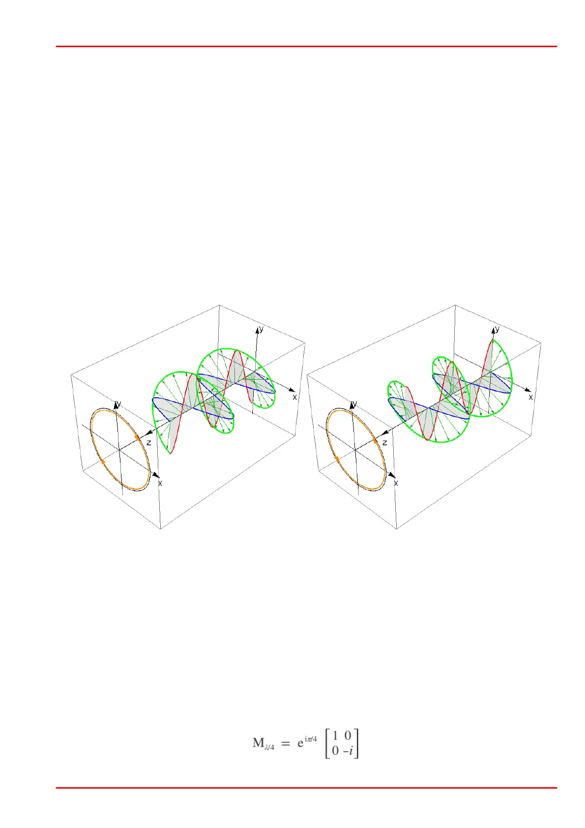
Right-Circularly Polarized Light
Left-Circularly Polarized Light
In above figures, the projection of the rotating E field vector on a virtual screen generates a
circle over time as the E field vector rotates clockwise (counterclockwise) representing right
(left) circular polarization.
Generation of Circularly Polarized Light
A circular polarization state can be generated using linearly polarized light and a quarter wave-
plate. When the E field vector of the incident linearly polarized light is oriented at a 45° angle to
the slow and fast axes of the quarter waveplate, the output light is circularly polarized. It is con-
venient to mathematically describe this transformation using matrix algebra, with Jones vectors
representing the polarized light and a Jones matrix representing the quarter waveplate.
The Jones matrix, describing a quarter waveplate with its slow axis oriented along the x (hori-
zontal) axis is:
The phase factor e
i
p
/4
can be omitted in almost all cases.
 Loading...


