© 2019 Thorlabs GmbH55
PAX1000
The Jones vector of a linear polarization state oriented at + 45° is written as:
When this linearly polarized light travels through a quarter waveplate, the Jones vector of the
output light can be calculated as follows:
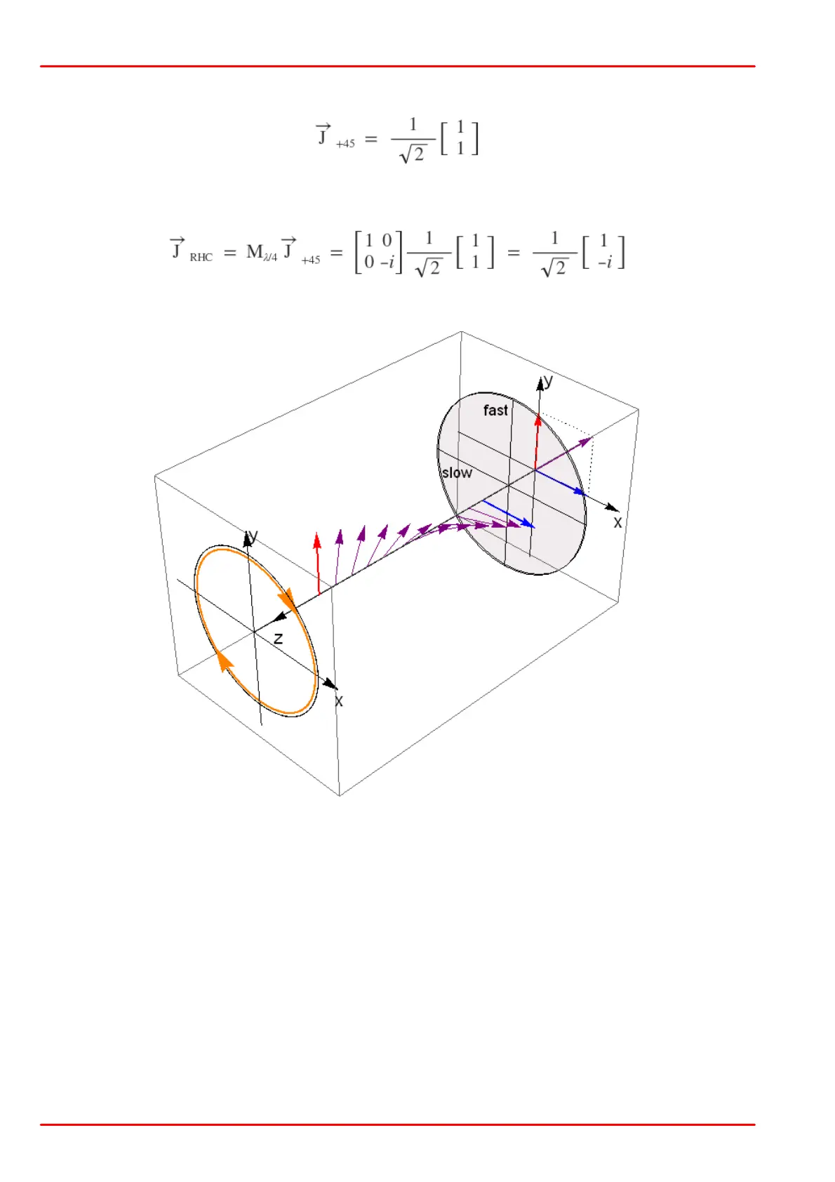
The output polarization is right-hand circular. The figure below illustrates this case:
The slow axis of the quarter waveplate are aligned with the x axis, and the fast axis of the QWP
is aligned with the y axis of the coordinate system. The input polarization is +45° linear and it is
transformed into a right-hand circular polarization.
The purple vector at the origin indicates the orientation of the incident +45° linearly polarized
light, while the red and blue vectors represent this E field decomposed into its orthogonal com-
ponents. These two components are in phase. The x axis component, which is represented by
the blue vector, is aligned with the slow axis of the waveplate and travels at a slower velocity
through the waveplate than the y axis component, which is aligned with the fast axis and rep-
resented by the red vector. Propagating through the waveplate, the phase of the x axis com-
ponent is retarded with respect to the phase of the y axis component. The amount of the retard-
ation is determined by the thickness of the waveplate. A quarter waveplate is designed to into-
duce a phase shift of -p/2. This retardation results in a right-hand circularly polarized output
light, and its E field vector rotates clockwise when it propagates along the z axis.

 Loading...


