© 2019 Thorlabs GmbH59
PAX1000
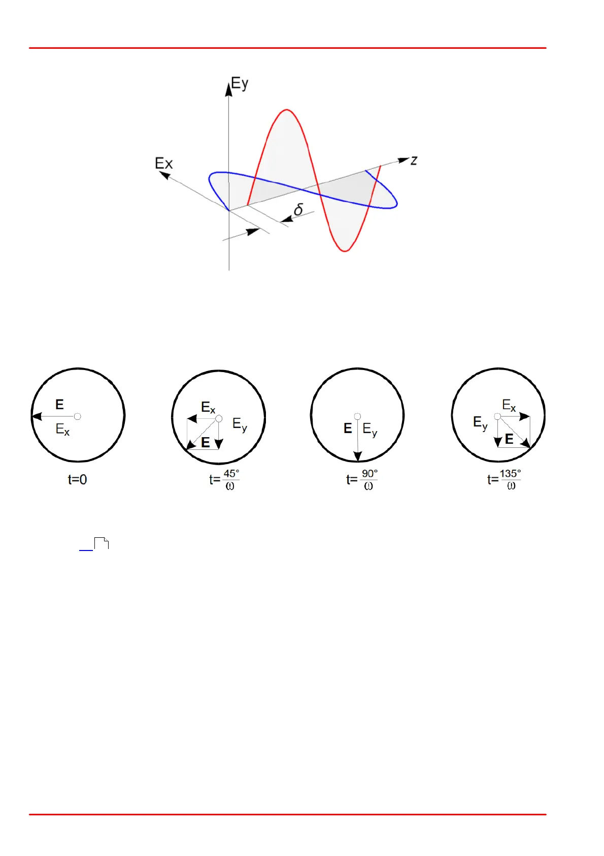
The vector of the electric field intensity E(t) is determined by the superposition of the X and Y
components. At a fixed time it points to a defined direction and has a defined magnitude.
The following figure is used to illustrate a case of circular polarization, in which Ê
x
=Ê
y
, d
x
=180°
and d
y
=90°.
Origin of a Circular Polarized Wave
When these values and the times noted beneath each of the following figures are inserted into
equation [1] , E
x
and E
y
values for each case can be calculated.
The vector sum of E
x
and E
y
is the total electric field intensity E. In this example, the head of
the vector moves anti-clockwise around the circumference of a circle as the wave propagates
toward the observer.
When Ê
x
¹Ê
y
, the electric field vector traces out an ellipse.
When the phase difference between the E
x
and E
y
components is 0°, instead of 90°, the circle
becomes a line, which corresponds to linearly polarized light.
58

 Loading...


