TC300 Heater Temperature Controller Chapter 4: Operational Elements
Rev B, January 5, 2022 Page 5
13. Analog Output of Channel 2 (ANLG2): 0 to + 5 V output proportional to the actual temperature of Channel
2; 0 V corresponds to the minimum temperature setting and + 5 V corresponds to the maximum temperature
setting of Channel 2.
14. Cooling Fan
15. Trigger of Channel 2 (TRIG) - When set to input: high level (+5 V) input will enable Channel 2, and low
level (0 V) input will disable it. When set to output: outputs high level (+5 V) when Channel 2 is enabled and
outputs low level (0 V) when Channel 2 is disabled.
16. Mono Jack Socket for External Sensor
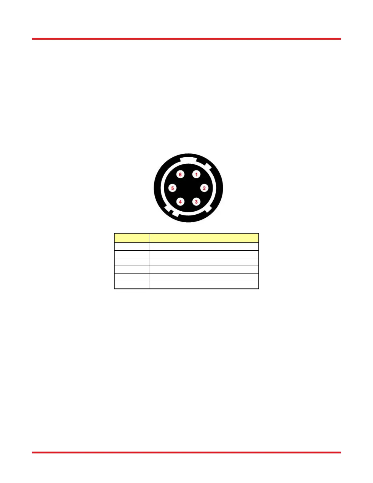
4.2. Hirose Connectors
On the front panel of the TC300, there are two 6-pin Hirose connectors. Each corresponds to an operation channel
of the TC300. The two connectors allow users to wire the heaters and various type of sensors to the TC300 for
temperature control operation. The detailed pin assignment is show below.
Pin No. Definition
Pin 1 Heater Output +
Pin 2 Heater Output -
Pin 3 Sensor + (4-Wire PT100/PT1000 only)
Pin 4 Sensor +
Pin 5 Sensor -
Pin 6 Sensor - (4-Wire PT100/PT1000 only)
Figure 2 Hirose Connector Pin Assignment
 Loading...