TC300 Heater Temperature Controller Chapter 4: Operational Elements
Page 4 CTN017856-D02
Chapter 4 Operational Elements
4.1. Front and Rear Panel
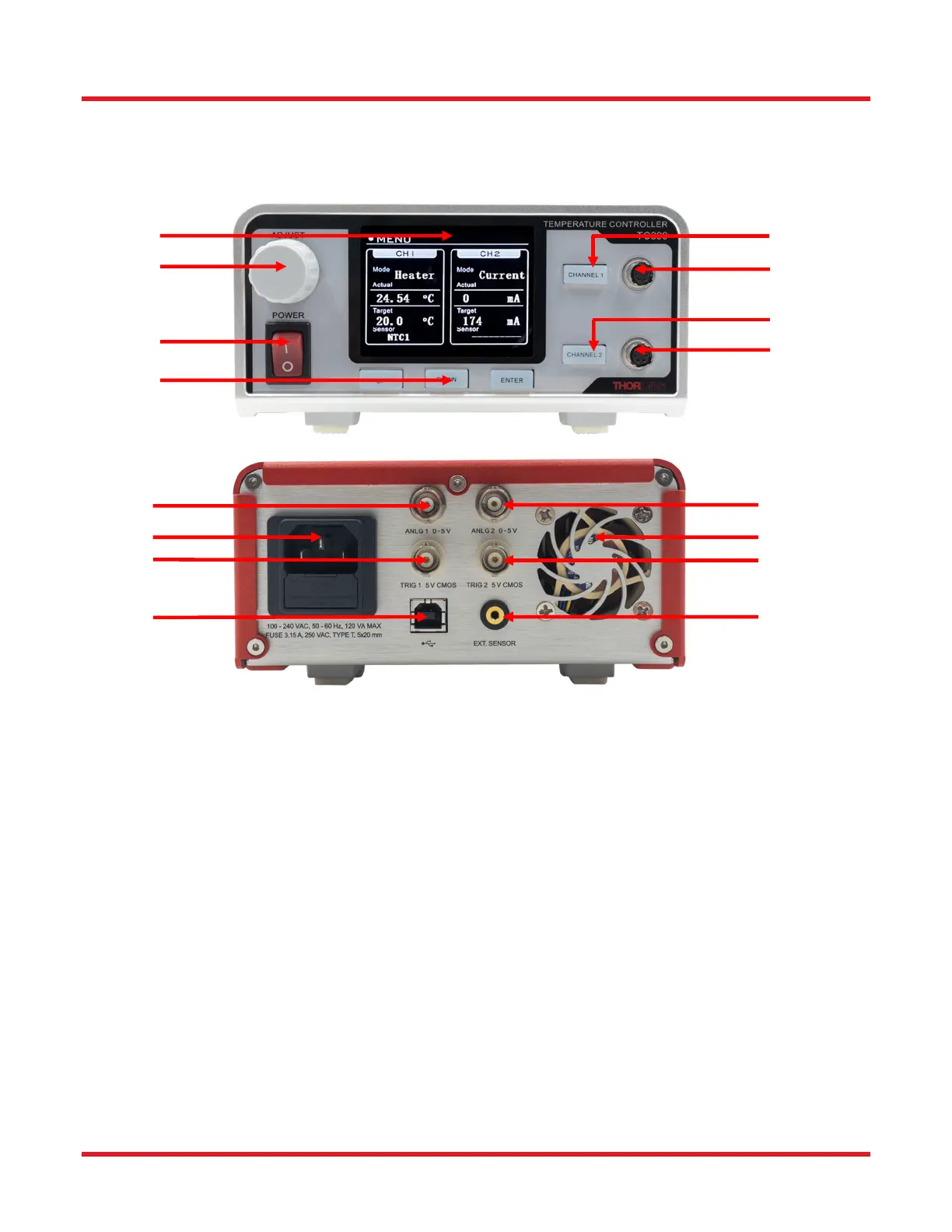
Figure 1 TC300 Front and Rear Panel
1. LCD Screen – When the device is switched on, the main user interface is display on the LCD.
2. Adjustment Knob – The knob can be used to navigate the user interface and change values.
3. Power Switch – Turns the unit on and off.
4. Keypads – Used to navigate the user interface.
5. Enable/Disable Button for Channel 1 - This button enables/disables Channel 1. The button is equipped
with a built-in LED indicator which lights on when Channel 1 is enabled and off when Channel 1 is disabled
6. 6-pin Hirose Connector for Channel 1 - For detailed pin assignment see Chapter 4.2.
7. Enable/Disable Button for Channel 2 - This button enables/disables Channel 2. The button is equipped
with a built-in LED indicator which lights on when Channel 2 is enabled and off when Channel 2 is disabled.
8. 6-pin Hirose Connector for Channel 2 - For detailed pin assignment see Chapter 4.2.
9. Analog Output of Channel 1 (ANLG1) - 0 to + 5 V output proportional to the actual temperature of Channel
1; 0 V corresponds to the minimum temperature setting and + 5 V corresponds to the maximum temperature
setting of Channel 1.
10. AC Input Connector
11. Trigger of Channel 1 (TRIG1) - When set to input: high level (+5 V) input will enable Channel 1, and low
level (0 V) input will disable it. When set to output: outputs high level (+5 V) when Channel 1 is enabled and
outputs low level (0 V) when Channel 1 is disabled.
12. USB Type B Connector – For software and command line operation. For more details, see Chapter 7 and
Chapter 8.
5
6
7
8
1
2
3
4
9
10
11
12
13
14
15
16
 Loading...