90
90
NV10P - Manual - 01 - 2015
CHARACTERISTICS
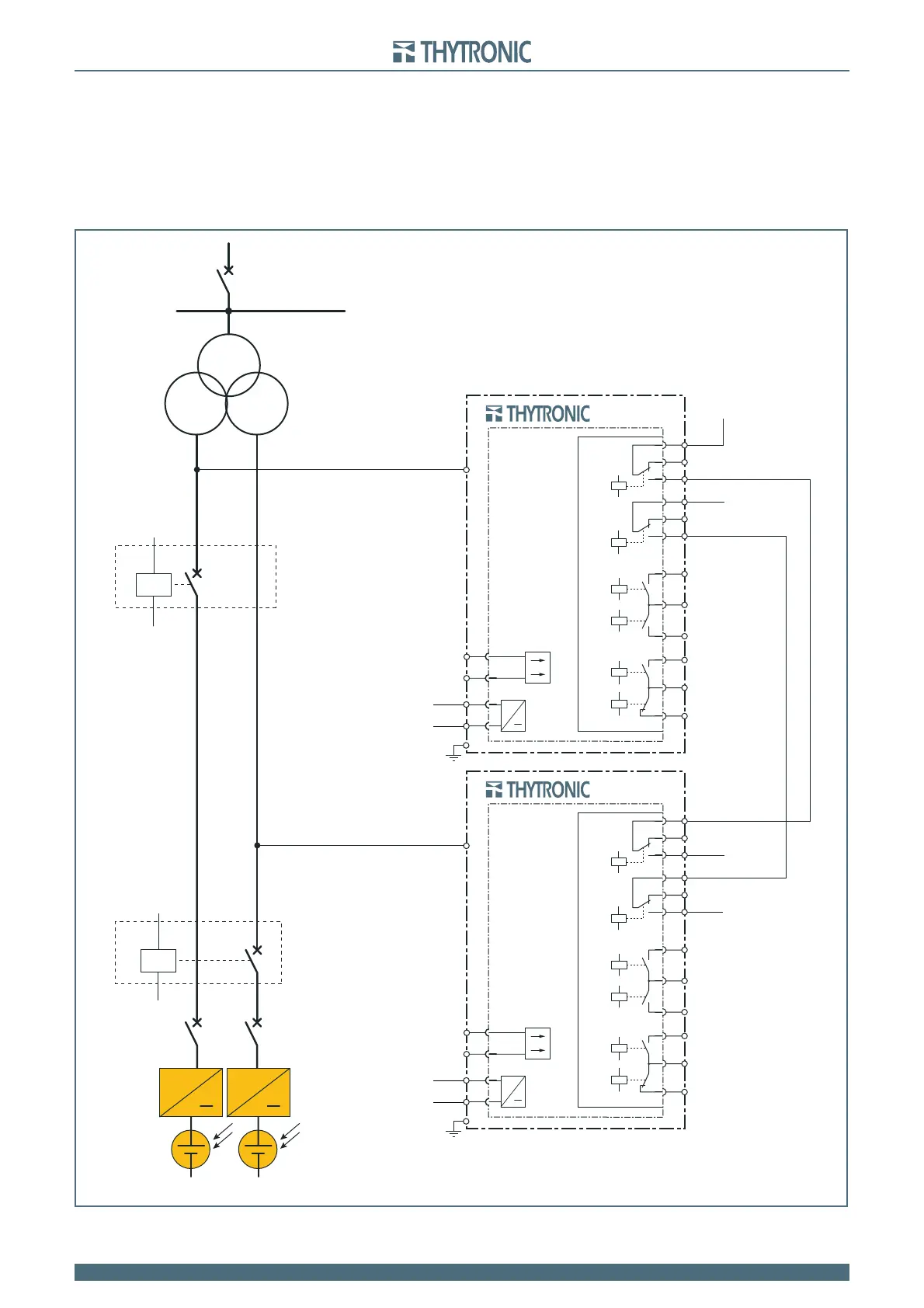
Example 2
The diagram shows the traditional solution that uses relays, logic inputs and pilot wires connections
to realize the logical OR for the opening command of two DDI (simultaneous control of both DDI oper-
ated by each interface relay).
The logical OR is realized driving each circuit breaker by the series connection of two output relays
(a relay for each CB); can easily understand the added complication for implementation of the logic
when further protection interfaces are mounted, (in addition the need to implement the logic con-
cerning the measurement of residual voltage, as described in Example 1, must be considered).
DI-A
DI-B
-U
AUX
-U
AUX
NV10P
+U
AUX
A9
A10
A11
A12
A13
A14
A3
A4
A5
A6
A7
A8
K2
K3
K4
K5
K6
K1
RELE’ FINALI
A19
A20
U
AUX
A1
≅
A2
IN1
U
L1
U
L2
U
L3
U
L1
U
L2
U
L3
NV10P
Trip - DI-A
Trip - DI-B
Trip - DI-A
Trip - DI-B
A9
A10
A11
A12
A13
A14
A3
A4
A5
A6
A7
A8
K2
K3
K4
K5
K6
K1
+U
AUX
RELE’ FINALI
A19
A20
U
AUX
A1
≅
A2
IN1
~ ~
-U
AUX
+U
AUX
-U
AUX
+U
AUX
Block diagram for the simultaneous opening of two interface Circuit Breaker (DI-A and DI-B) made by one or both NV10P relays