SAWMILL ASSEMBLY
Saw Head Installation
3
3-22 15doc110819 SAWMILL ASSEMBLY
12. Place the shaft end with the sprocket in the up/down bracket fastened earlier at the control box.
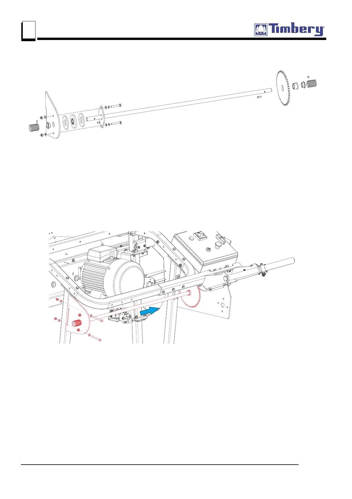
Next, use the M8x70 bolts to install the other up/down bracket to the mast frame on the opposite
side of the saw head. Bolt the friction torque limiter to this bracket with the M8x50 bolts. Be careful
not to tighten the bolts too much; it can cause greater resistance when the up/down crank is being
used. Now that the up/down shaft with all necessary parts has already been placed in the up/down
brackets, insert the left and right bushings for the lift cable onto the ends of the up/down shaft and
secure with the hex socket head cap screws. (See the figure below.)
13. Insert the shaft with sprocket through the dial hole and put the chain on the shaft. Place the other
side of the chain on the up/down shaft sprocket. Connect the chain ends with the master link. Then
bolt the dial to the up/down bracket located at the control box. Install the up/down crank. It is impor-
tant that the up/down crank be square with the dial. The distances A and B must be the same at


 To Next Page