16
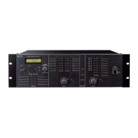
Thegurebelowshowsasignalow.
9.2. Assignment Switches of INPUTs ST1 and ST2
It is possible to assign Stereo inputs 1 and 2 to Outputs 1 through 4.
Pressing each Assignment switch causes the corresponding indicator to light, routing the input signal as shown
in the table below.
Assignment switch Output destination Signal
1 OUTPUT 1 L channel
2 OUTPUT 2 R channel
3 OUTPUT 3
L+Rchannel
4 OUTPUT 4
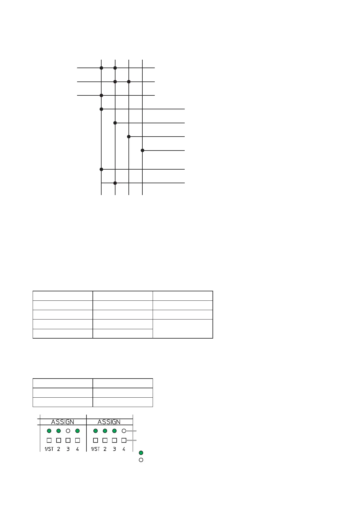
[Assignment setting example]
Set the Assignment switches of the inputs as the table below.
Input Assignment switch
STEREO INPUT 1 1, 2, 4
STEREO INPUT 2 1, 2, 3
STEREO INPUT 1 STEREO INPUT 2
: Unlit
: Lit
Assignment switch
Assignment indicator
Note
Use a ne-tipped object to
press in the Assignment switch.
Assignment switch
Input
MONO INPUT 1
MONO INPUT 2
MONO INPUT 3
OUTPUT 1
(Outputs the mixed signal of MONO INPUTs 1 and 3)
OUTPUT 2
(Outputs the mixed signal of MONO INPUTs 1 and 2)
REC OUT R*
(Outputs the mixed signal of MONO INPUTs 1 and 2)
REC OUT L*
(Outputs the mixed signal of MONO INPUTs 1 and 3)
OUTPUT 3 (Outputs the MONO INPUT 2 signal)
OUTPUT 4 (No signal)
1 2 3 4
Set the REC OUT assignment using the supplied M-864D PC Software.
The REC OUT default assignment is as follows.
REC OUT L: Assignment switch 1
REC OUT R: Assignment switch 2
*
 Loading...