41
22. INSTALLATION
22.1. Installation Precautions
Be sure to leave the installation work (rack mounting) to a
qualiedinstaller.
(When rack mounting screws are supplied)
The supplied rack-mounting screws can be used for
the TOA equipment rack only. Do not use them for
other racks.
When installing the unit in a rack other than that of
TOA, be sure to use the screws with a diameter of
over 5 mm (0.2”) and length of over 12 mm (0.47”) to
mount the unit.
Failure to do so may cause the unit to fall, resulting in
personal injury.
(When rack mounting screws are not supplied)
Rack mounting screws are not supplied with the unit.
Be sure to use the screws with a diameter of over 5
mm (0.2”) and length of over 12 mm (0.47”) to mount
the unit.
Failure to do so may cause the unit to fall, resulting in
personal injury.
CAUTION
When installing the unit in an equipment rack, do not
block the ventilation slots on the unit’s both sides and
rear side. Doing so may cause heat to build up inside
theunitandresultinre.
CAUTION
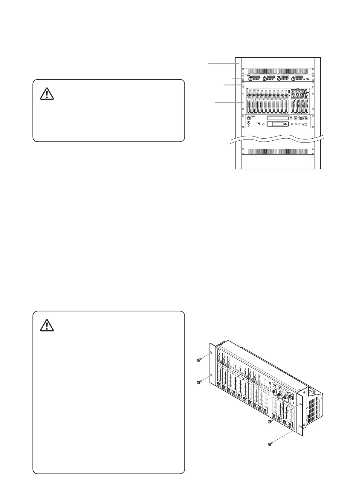
22.2. Rack Mounting
• Elevated Operating Ambient - If installed in a closed or multi-unit rack assembly, the operating ambient
temperature of the rack environment may be greater than room ambient. Therefore, consideration should be
given to installing the equipment in an environment compatible with the maximum ambient temperature (Tma)
speciedbythemanufacturer.
• ReducedAirFlow-Installationoftheequipmentinarackshouldbesuchthattheamountofairowrequired
for safe operation of the equipment is not compromised.
• MechanicalLoading-Mountingoftheequipmentintherackshouldbesuchthatahazardousconditionisnot
achieved due to uneven mechanical loading.
• Circuit Overloading - Consideration should be given to the connection of the equipment to the supply
circuit and the effect that overloading of the circuits might have on overcurrent protection and supply wiring.
Appropriate consideration of equipment nameplate ratings should be used when addressing this concern.
• ReliableEarthing-Reliableearthingofrack-mountedequipmentshouldbemaintained.Particularattention
should be given to supply connections other than direct connections to the branch circuit (e.g. use of power
strips)."
DIGITAL
STERE O
MIXER
M-864 D
PEAK
0dB
-40dB
LOW CUT
FBS
TONE/GAIN
1
1
10
9
8
7
6
5
4
3
2
2
10
9
8
7
6
5
4
3
2
3
10
9
8
7
6
5
4
3
2
4
10
9
8
7
6
5
4
3
2
5
10
9
8
7
6
5
4
3
2
6
10
9
8
7
6
5
4
3
2
I N P U T
O U T P U T
7
10
9
8
7
6
5
4
3
2
8
10
9
8
7
6
5
4
3
2
ST
1
10
9
8
7
6
5
4
3
2
ST
2
10
9
8
7
6
5
4
3
2
1
10
9
8
7
6
5
4
3
2
2
3
4
1
2
3
4
1
2
3
4
1 2
3
4
1 2
3
4
1 2
3
4
1
2
3
4
1 2
3
4
1/ST
2
3
4
1/ST
2
3
4
ASSIGN
PEAK
0dB
-40dB
LOW CUT
FBS
TONE/GAIN
ASSIGN
PEAK
0dB
-40dB
LOW CUT
FBS
TONE/GAIN
ASSIGN
PEAK
0dB
-40dB
LOW CUT
FBS
TONE/GAIN
ASSIGN
PEAK
0dB
-40dB
LOW CUT
FBS
TONE/GAIN
ASSIGN
PEAK
0dB
-40dB
LOW CUT
FBS
TONE/GAIN
ASSIGN
PEAK
0dB
-40dB
LOW CUT
FBS
TONE/GAIN
ASSIGN
PEAK
0dB
-40dB
LOW CUT
FBS
TONE/GAIN
ASSIGN
PEAK
+12
+6
-
6
-
12
-
24
-
40
dB
0
2
10
9
8
7
6
5
4
3
2
PEAK
+12
+6
-
6
-
12
-
24
-
40
dB
0
3
10
9
8
7
6
5
4
3
2
PEAK
+12
+6
-
6
-
12
-
24
-
40
dB
0
4
10
9
8
7
6
5
4
3
2
PEAK
+12
+6
-
6
-
12
-
24
-
40
dB
0
PEAK
0dB
-40dB
MONO
TONE/TRIM
ASSIGN
L
R
PEAK
0dB
-40dB
MONO
TONE/TRIM
ASSIGN
L
R
ST2
INPUT
ARC
REC OUT
BASS
GAIN
VOL
MID
PAD
VOL
REBLE
RUN
LOCK
REMOTE
LOCAL
ON
POWER
OFF
PHANTOM
VOL
3
4
2
PRESET
1
Power amplifier
Rack
M-864D
Blank panel