Document Ref 941113-001 Rev 2 Page 2-3
Quantium 310 Maintenance Manual Maintenance Procedures - General
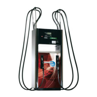
•Side B of the dispenser has air vent holes in the drip tray at the base of the dispenser. Side
B houses the hydraulics and fuel inlet connections, visible once the front panel is removed.
With the calculator head opened, side B has the centre plate cover.
Side A
Side B
2.3 Identification of Side A
The different sides of the dispenser referred to in this manual are described as follows:-
•Side A of the dispenser has no air vent holes in the drip tray. All single hose models have
the hose on the right hand side when facing side A. With the calculator head opened, side
A houses the battery and the programming of the calculator.
Air Vent
holes in driptray