Maintenance Procedures - Hydraulic Quantium 310 Maintenance Manual
Page 4-18 Document Ref 941113-001 Rev 2
INSTRUCTIONS
1) Follow the instructions given in sections 2.4 and 2.6 to gain access to the hydraulic area
and the cable glands.
2) Using a 6mm allen key, loosen and remove the ten bolts on the
junction box cover on side B of the dispenser. Remove the
junction box cover completely.
3) Identify the motor to be replaced.
4.10 Changing the motor
Before starting the maintenance procedure, please refer to section 2.
The motor is accessed from both sides of the dispenser (see section 2.3 for the identification
of the dispenser sides) and the cabling requires access to the calculator head.
Tools required
•Replacement motor including cables and bracket (refer to the Parts Manual for exact part
identification)
•10mm, 13mm and 32mm spanners
•Small screwdriver
•6mm allen key
•Wire cutters
•Replacement Weights & Measurements seals
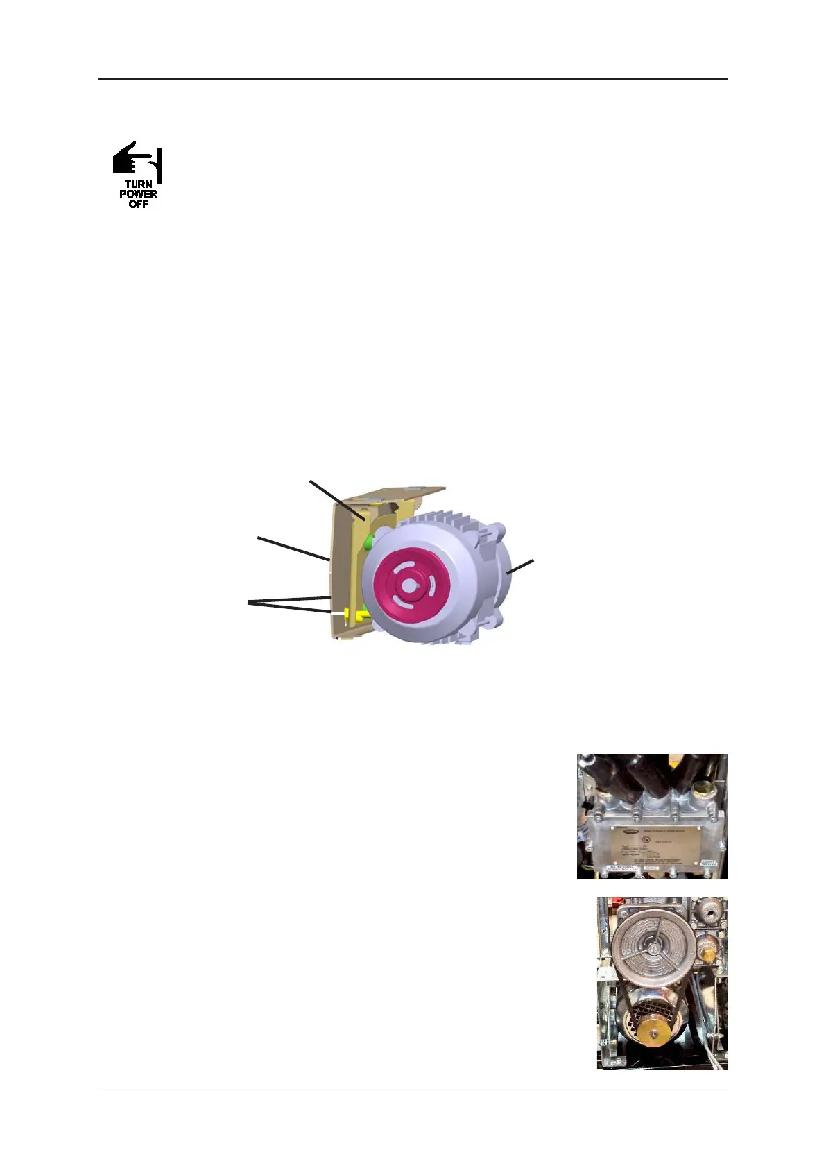
Description of Parts
MOTOR
V-BELT
TENSION
SCREWS
MOTOR BRACKET
PUMP
SUPPORT
BRACKET