Document Ref 941113-001 Rev 2 Page 5-21
Quantium 310 Maintenance Manual Maintenance Procedures - Electronics
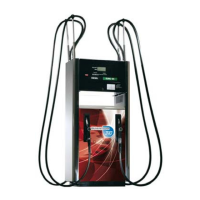
5.11 Replacing the Programming Switch
Before starting the maintenance procedure, please refer to section 2.
Ensure the dispenser is isolated and all power is turned off.
The Programming Switch is accessed from side B of the calculator head (see section 2.3
for the identification of the dispenser sides).
Tools required
•Replacement Programming Switch (refer to the Parts Manual for exact part identification)
•Small flathead screwdriver
•5.5mm nut runner
Description of Parts
INSTRUCTIONS
1) Follow the instructions given in section 2.5 to gain access to the calculator head.
2) Locate the programming switch on side B of the calculator
head.
3) Trace the programming switch cable to the mainboard on side A of the dispenser.
4) Disconnect the programming switch connector from the
mainboard.
5) Use a small flathead screwdriver to remove the
programming switch cable from the connector.
Note: Take care to note the position of the cable wires
in the connector.
PROGRAMMING
SWITCH
PROGRAMMING
SWITCH BRACKET