Document Ref 941113-001 Rev 2 Page 6-5
Quantium 310 Maintenance Manual Maintenance Procedures - VR
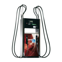
6.3 Replacing the motor on the ECVR Unit
Before starting the maintenance procedure, please refer to section 2.
The motor is accessed from both sides of the dispenser (see section 2.3 for the identification
of the dispenser sides).
Tools required
•Replacement motor (refer to the Parts Manual for exact part identification)
•13mm and 10mm spanners
•6mm and 2mm allen keys
•Small flathead screwdriver
•Wirecutters
Description of Parts
INSTRUCTIONS
1) Follow the instructions given in section 2.4 to gain access to the hydraulic area.
2) Using a 6mm allen key, loosen and remove the ten bolts on the
junction box cover on side B of the dispenser. Remove the
junction box cover completely.
3) From side B of the dispenser, identify the motor power cable
and trace to the junction box.
Note : the cable has an identification tag at each end.
4) Cut the cable ties using wirecutters and loosen the relevant gland.
5) Using a small flathead screwdriver, disconnect the motor power
cable in the junction box.
6) Pull the motor cable through from the junction box to the motor.
V-BELT
FOUR BOLTS
ON MOTOR
MOTOR PULLEY
FOUR BOLTS
ON BRACKET