Maintenance Procedures - VR Quantium 310 Maintenance Manual
Page 6-6 Document Ref 941113-001 Rev 2
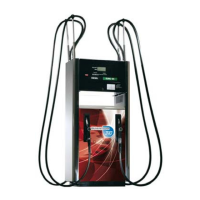
7) Identify the relevant side panel to remove to access the motor
control cable. Remove the bolts holding the side panel in position.
Prise the left side of the panel from the frame, slide the panel
towards the right then remove the panel completely.
Note : there may be a requirement to lift the panel up slightly.
8) Trace the cable up the relevant side of the dispenser to the calculator
head. Cut the cable ties using wire cutters and loosen the relevant
gland.
Note : the cable has an identification tag at each end.
9) Follow the instructions given in section 2.5 to gain access to the calculator head. Locate
the ECVR circuit board.
10) Using a small flathead screwdriver, disconnect the motor control cables (positive and
negative) from the ECVR circuit board in the calculator head.
11) Pull the motor control cable down from the calculator head, through the unit, to the motor.
Note : ensure that the cables are only attached at the motor end.
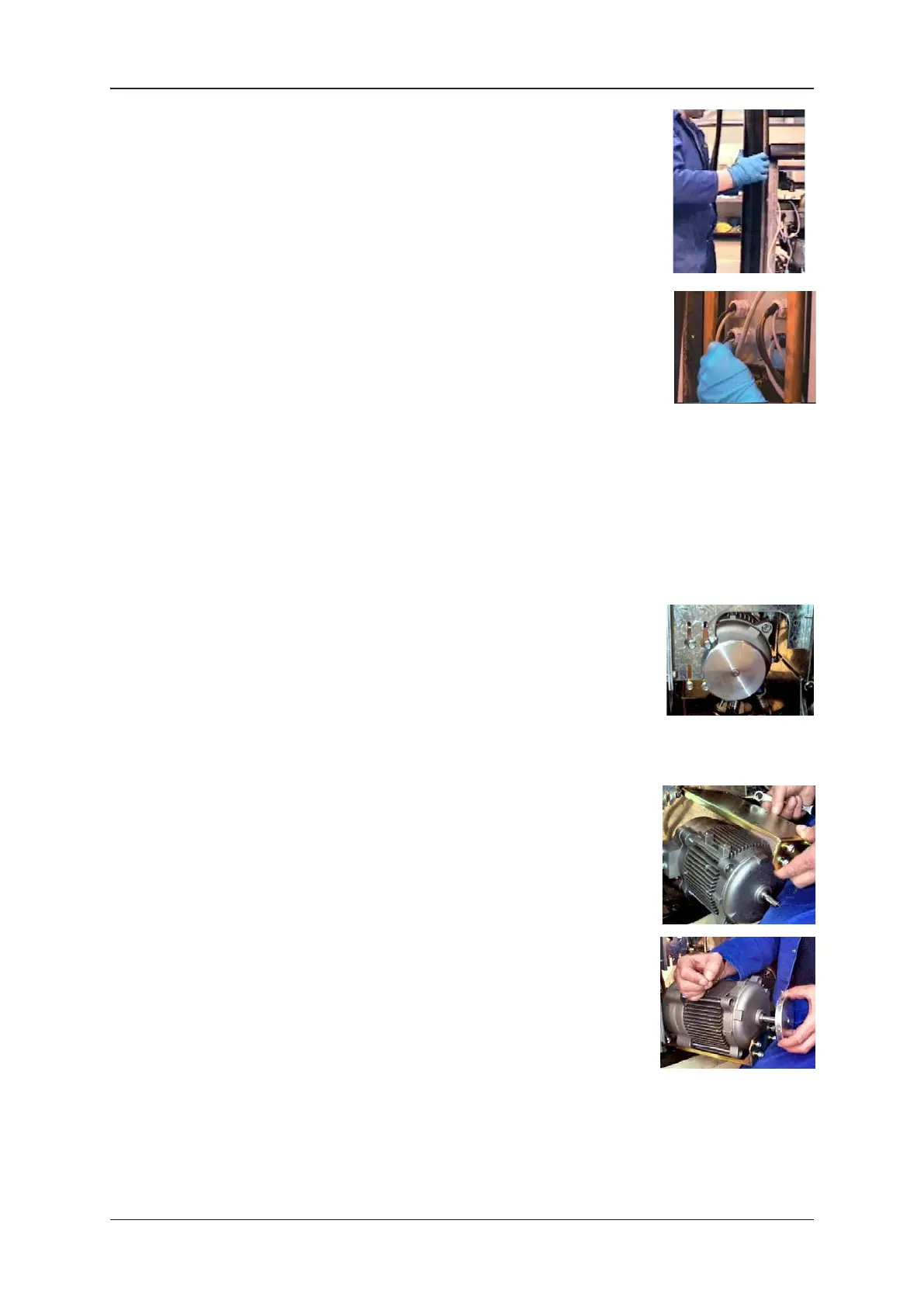
12) Using a 10mm spanner, loosen the four bolts on the motor on side
A of the dispenser. The motor will drop down into the slots, held
in place by the top two bolts.
Note : support the motor during this procedure.
13) Follow the instructions given in section 6.1 to remove the ECVR motor v-belt.
14) Push the motor towards side B of the dispenser to release it. Lift
out the motor from the unit.
15) Using a 13mm spanner, loosen and remove the four bolts on the
motor bracket. Remove the bracket completely.
16) Using a 2mm allen key, loosen and remove the motor pulley.
17) Using a 2mm allen key, fix the motor pulley to the new motor.
18) Using a 13mm spanner, fix the bracket to the new motor.
19) Position the new motor into the unit, locating the four bolts in
the slots.
20) Lift up the motor into the raised position and re-fit and adjust the v-belt as described in
section 6.1.
Note : support the motor during this procedure.