Document Ref 941113-001 Rev 2 Page 4-19
Quantium 310 Maintenance Manual Maintenance Procedures - Hydraulic
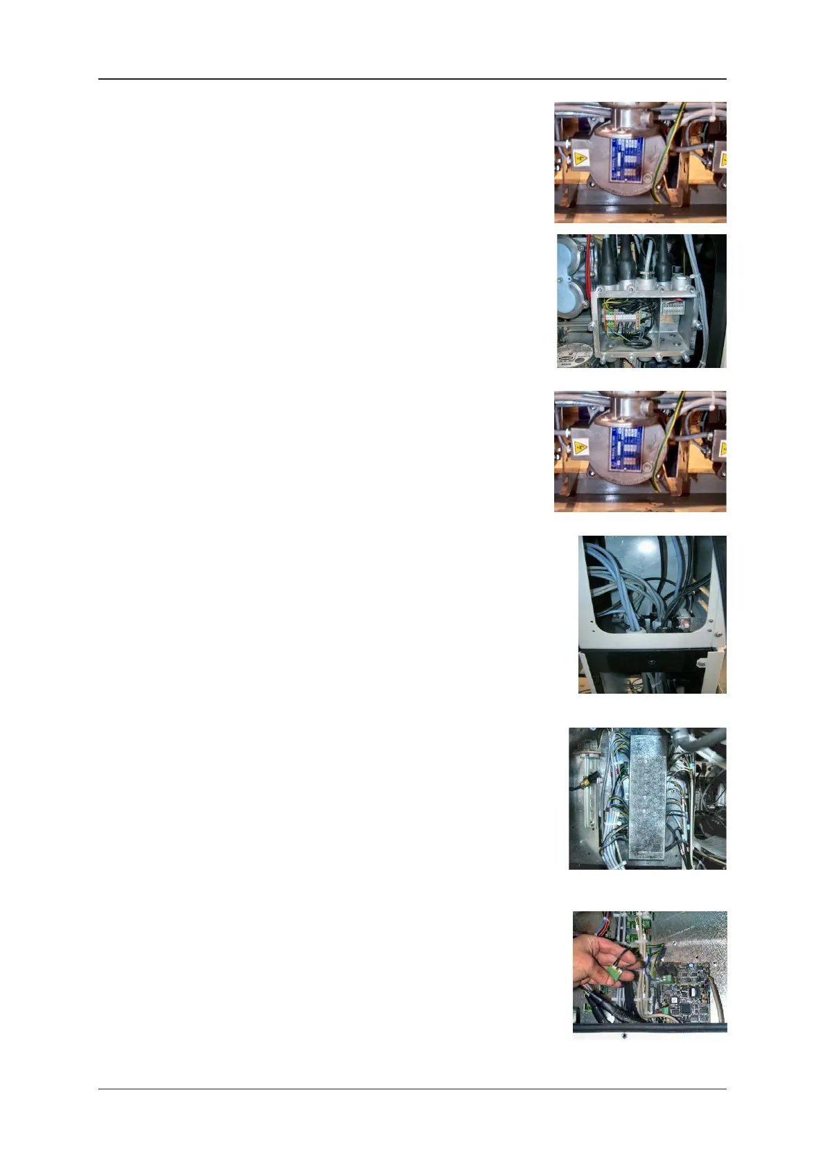
4) From side B of the dispenser, identify the motor power
cable and trace to the junction box.
Note : the cable has an identification tag at each end.
5) Cut the cable ties as required using the wire cutters. Push
up the sheath covering the relevant cable and gland and
loosen the gland in the junction box using a 32mm spanner.
6) Using a small screwdriver, disconnect the motor power cable
in the junction box.
7) Remove the motor power cable from the junction box,
remove the sheath completely and pull the cable through
to the motor.
8) Follow the instructions given in section 2.5 to gain access
to the calculator head.
9) From side B of the dispenser, identify the motor control
cable and trace to the calculator head.
Note : the cable has an identification tag at each end.
10) Cut the cable ties as required using the wire cutters. Using a
32mm spanner, loosen the relevant glands inside the hose
management system and inside the calculator head.
11) If a centre plate cover is fitted, break the W&M seal using
the wire cutters.
12) Using a screwdriver, loosen and remove the screw on the
centre plate cover. Remove the centre plate cover completely
to gain access to the motor control connection.
13) Disconnect the motor control cable connection from the
mainboard in the calculator head.
Note : remember the position of this connection.
14) Using a small screwdriver, remove the connector from the
motor control cable.
15) Pull the motor control cable down from the calculator head
through the unit to the motor.