10. Application Examples
Page 57
Status: 5.12.17
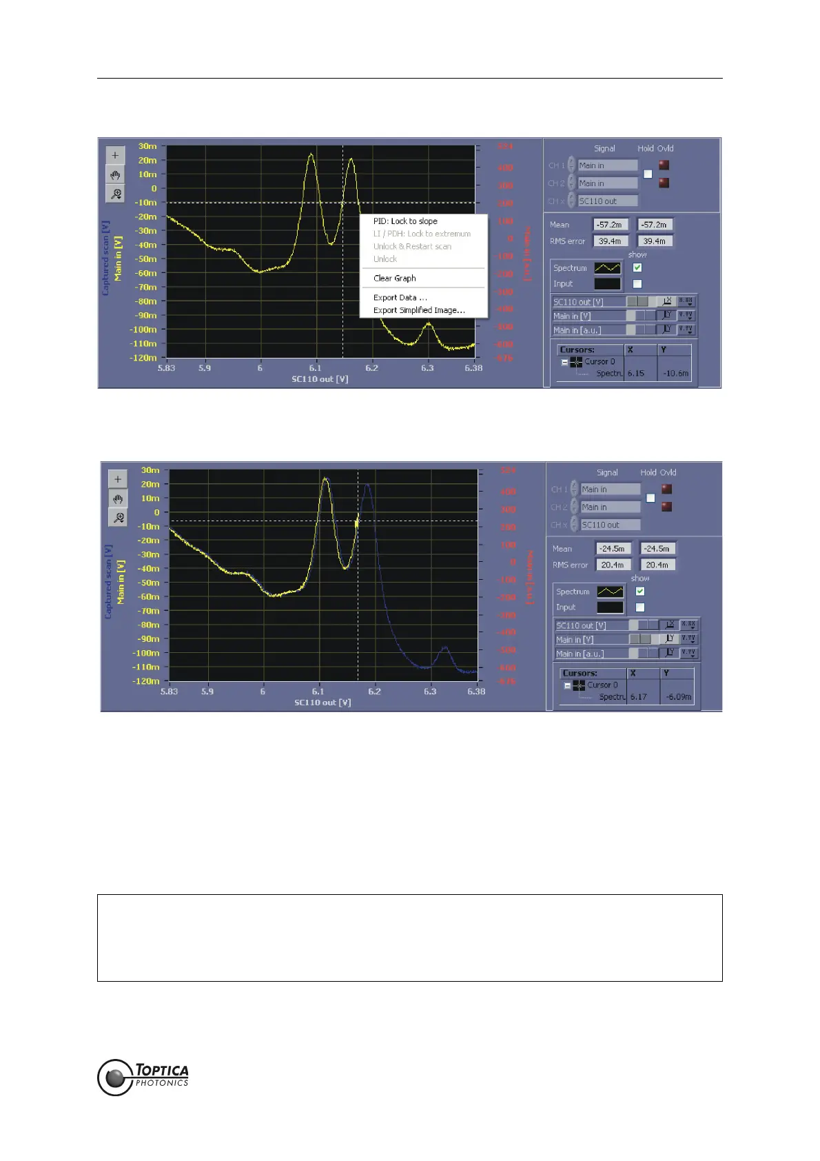
Figure 44 Initiating the AutoLock to a slope of the absorption signal
Figure 45 Autolock display just after the lock is engaged (PID: lock to slope)
20. After some time the yellow trace disappears and a scatter plot is left which indicates both the
input signal (y-axis) and the current output of the PID 2 which in this case coincides with the scan
(see Figure 46) on the x-axis. The calculated rms deviation from the setpoint value displayed in the
right panel can be used to optimize the lock.
To turn the lock off, perform a right mouse click in the AutoLock display graph and select either Unlock to
just release the lock or Unlock & Restart scan to release the lock and immediately start scanning again.
NOTE ! The behavior of the output value of the PID controllers when switching off the lock can be
configured by the user in Settings:PID:Turn-off reset behavior for Manual and AutoLock,
respectively. Either the PID controller output is set to zero or its current value is transferred
to the offset value of its output channel. The latter setting leads to the scan being cen-
tered at the last output value (see section 8.2.5.1 for details)
 Loading...