Feedback Controlyzer DigiLock 110
Page 56
Status: 5.12.17
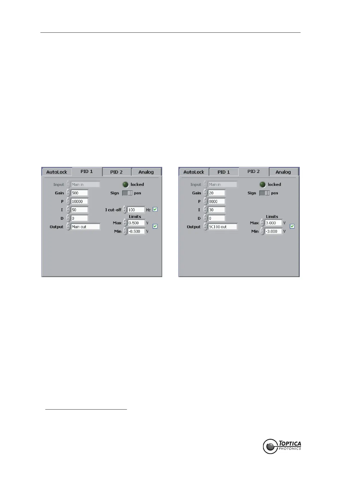
17. To configure the PID controllers, select the PID 1/PID 2 tab (see Figure 11 and Figure 13) to access
the corresponding parameters (see Figure 43). A valid strategy is to first implement PID 2 for initial
locking (setting the Gain of PID 1 to zero) and then add PID 1 to improve the lock at higher fre-
quencies. In AutoLock mode the input channel of the PIDs is defined by the AutoLock input. PID 1
is used for the high frequency feedback, therefore its output channel is <Main out> which is con-
nected to the modulation input of the laser. PID 2 is used for large range, low frequency feedback
to the piezo. To prevent the controllers from mutual interaction, the PID 1 features an “I cut-off“ fre-
quency. The “I cut-off“ frequency defines the corner frequency below which the integral gain of
the controller is limited. A reasonable choice is in the order of 100 Hz.
18. The values of the gain parameters for the PIDs shown in Figure 43 are set in the corresponding tabs.
Their settings depend on the slope of the error signal and the actuator response. For the given
setup the error signal amplitude should be on the order of 100 mV
pp
,see above for input offset
and gain. In most cases the low frequency feedback of PID 2 is sufficient to achieve a first lock
11
. It
is advisable to start with conservative gain settings. To find the correct settings of the sign for each
PID controller, please see section 9.4. Once locking is accomplished the parameters can be opti-
mized (see section 9.3).
Figure 43 PID Setup for locking to the slope of a Doppler-free Rb peak
19. Before the lock is initiated, the lock point must be selected by dragging the crosshairs in the graph
of the AutoLock display to the desired position. When you drag the vertical line in the horizontal
direction the crosshairs will follow the current trace. Once chosen, the crosshairs will automatically
track the lock point while the laser might slowly drift. To engage the lock, click the right mouse but-
ton and choose PID: Lock to slope from the context menu (see Figure 44). Starting with the next
trigger the trace captured is displayed in a different color (here yellow) while the held trace is visi-
ble (here blue
12
). Once the lock point is reached the trace stops and the lock is activated. Figure
45 shows the AutoLock display some seconds after the lock has been triggered.
11. The output of the controllers can be restricted using the Limits settings (section 8.2.1.4 and 8.2.1.5), e.g. to about the scan
range. This helps to avoid destabilization of the laser by driving it very far from the lock point, especially during initial setup
and optimization.
12. The colors of the traces can be changed by the user. To restore the factory settings, load the default profile.
 Loading...