10. Application Examples
Page 55
Status: 5.12.17
15. First the AutoLock module is activated and the controllers PID 1 and PID 2 are selected by check-
ing the corresponding boxes (see Figure 40). PID 1 will handle the high frequencies (by controlling
the laser current via the modulation option in the laser head) whereas PID 2 will be responsible for
the lower frequencies by controlling the piezo voltage. As input channel select <Main in> where
the photodetector signal enters the module. In AutoLock mode the input channel chosen in the
AutoLock tab (see Figure 11) is taken as input for all the selected controllers.
16. To use the AutoLock, change the display from Scope to AutoLock. The x-axis of the display is the
output of the Scan module and the y-axis is the corresponding value of the selected AutoLock
input channel.
In the AutoLock mode the software will actually perform a hardware zoom and pan, i.e. modify the scan
amplitude of the Scan module and the offset of the corresponding output channel according to the dis-
played x-axis.
To graphically and interactively magnify the part of the absorption spectrum in the vicinity of the
desired lock point: Select the “x-axis Zoom“ tool (see Figure 41), place the cursor left of the desired x-
value, hold the left mouse button, move the mouse to the right of the desired x-value and release the left
mouse button.
Figure 41 Available tools for the graph displays
To increase the scan range again use the “Zoom out“ tool: The graph will zoom as long as you press the
left mouse button. To shift the spectrum to the left or right (i.e. modifying the offset) use the Pan (hand)
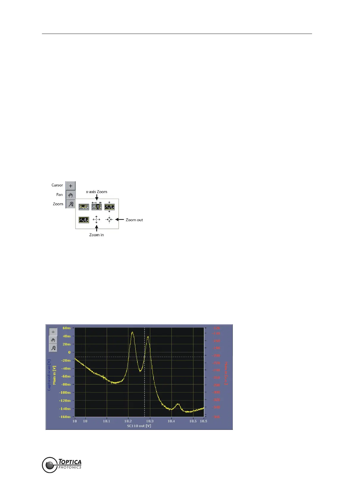
tool. In our example the
85
Rb D2 transitions at 780 nm are used (Figure 42) and the locking point is chosen
to be at the rising slope of the second peak by dragging the crosshairs. Note that the behavior of the
lockpoint selection can be customized in detail in the settings of the Autolock|Advanced tab (see Figure
11). The options are explained in section 8.2.5.1. Here, the following settings are assumed:
Cursor: Track on, Snap to Setpoint: off, Smart Assistance: Engage on, Setpoint: on.
Figure 42
85
Rb D2 transitions at 780 nm. The crosshairs mark the currently selected locking point
 Loading...