15
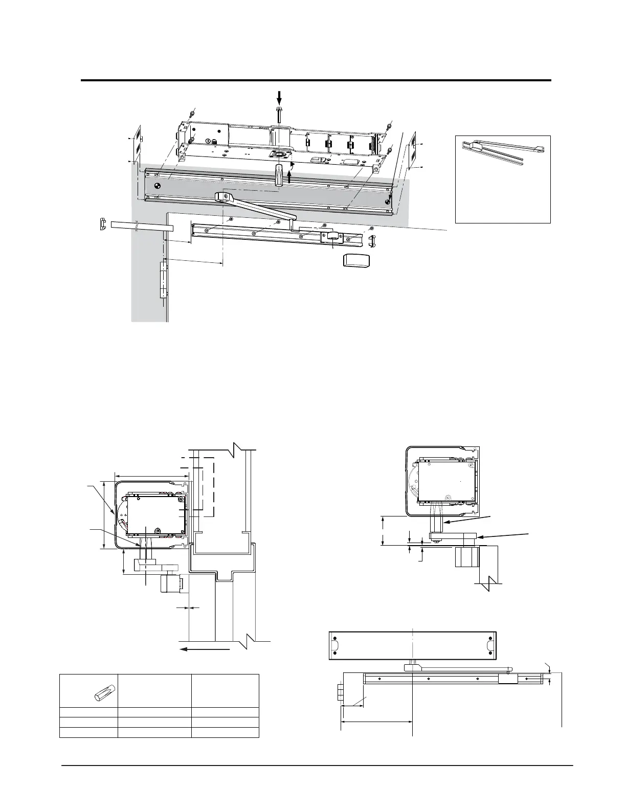
Inswing (Pull) Arm 0” Reveal Installation
Standard Inswing Arm
0” Reveal, P/N 407456
13.77 in. (350 mm
1) )
1) Determine the handing of the operator according to
the door. Note that arrow on operator indicates
opening direction of rotation.
2) Locate & mark output shaft location 12-3/16” from
CL of hinge onto door frame as
3) Determine header mounting height = X. See below.
4) Bolt header to the wall with appropriate hardware.
5) Locate and mount door arm slide track onto the door at
4” from C/L of pivot, mounting holes 5/8” from top of the
door as shown below.
6) Insert shaft/ drive arm into the operator, leave shaft bolt
loose until appropriate step during commissioning
procedure.
7) Proceed to page 16 to perform commissioning.
Part No.
141032 (STD)
141205
141020
Shaft Length
3-
7/32” [82mm]
4-
27/32” [123mm]
2-
5/8” [67mm]
X
1-
3/4”” (44mm]
3-
3/8” [86mm]
1-
5/32” [29mm]
For extended reveals contact TORMAX
Preferred
Primary
Power
12-
3/16
”
[310mm]
4”[102mm]
5" [127]
4 9/16" [116]
C
L
X
Electrical
Controls
SWING DIRECTION
SWING
DOOR
ACCESS
COVER
TORMAX
1102, 1201
OPERATOR
X: Mounting height (distance bottom of header to top of door)
0” Reveal
Door Arm
407456
12-3/16” [310]
5/8” [16]
4”
[102]
Header
C/L
Pivot
Butt Hingle or Offset Pivot
C/L
Shaft
Standard
Shaft 141032
3-7/32” (82mm)
1/8” [3]
3/16” [5]
1-7/8” [48]
Standard Aluminum Arm
Stainless Steel Arm
TORMAX
1102, 1201
OPERATOR
Top of
the Door
S.S. Shaft
PT# US801966
S.S. 0” Reveal
Inswing Arm
PT# US801996
 Loading...