52
TECHNICAL SPECIFICATIONS
L
N
Electrical Requirements for Installation Personnel
Have a licensed electrician:
• Make all mains primary power connections in accordance to federal, state and local regulations.
• Route mains primary power from power distribution panel (10 amp circuit breaker minimum
per operator) to the operator.
• Install a service switch or emergency shut OFF switch, if required by customer or per regulations.
This is in addition to the mains circuit breaker to interrupt power, switch must be rated @ 10 amp
minimum.
Mains Connection
Connection: N + L1 + PE protected on site with 10 AT, protective earth necessary
Power rating: 1 x 230 / 1 x 115 V AC (+5 %/ – 10 %) 50– 60 Hz, max. 200 W
Supply cable: Type H05VV-F, H05RR-F or flexible cord of type S, SO, SJ, SJO, ST, STO, SJT,
SJTO or AFS
10AT
L1
3mm
N
230/115V~
50/60 Hz
T1132/1
Before beginning the work described below, check that the mains primary power is
switched off. If required
place “Out of Service” tag on circuit breaker or service switch.
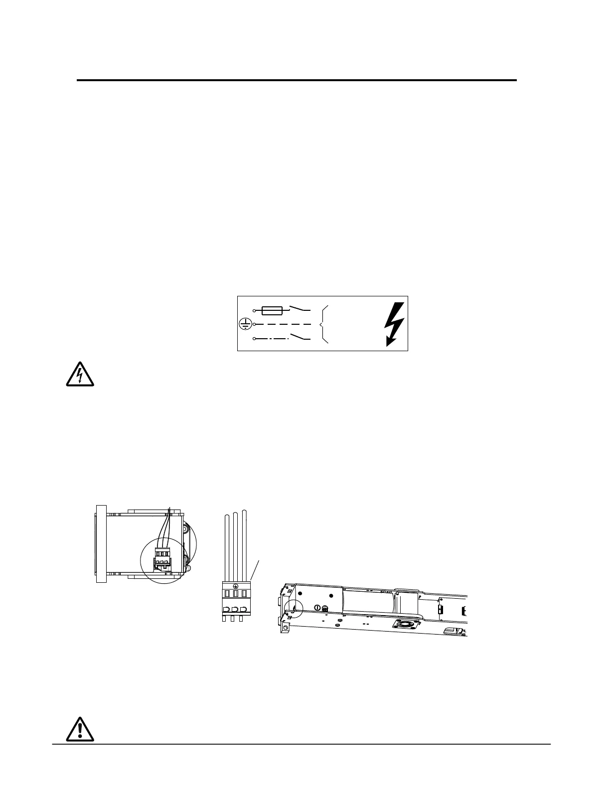
• Route the mains connection to the operator along the side of the power supply.
• The edges must be rounded off on all bushings for the mains connection.
• Route mains cable either through the header end cap or through header back plate.
• Use only cable bushings made from synthetic materials Metallic bushings must be grounded.
• Connect mains cable to terminal (1) as shown in the illustration.
• Secure mains cable with a cable strap at a synthetic lug on the base plate.
• Do not apply power to the door until ready for commissioning.
• A system switch (FCP or 3-position switch) must be on site.
Secure mains cable properly to prevent it from getting into the moving parts of the operator
or door system.
1
 Loading...