19
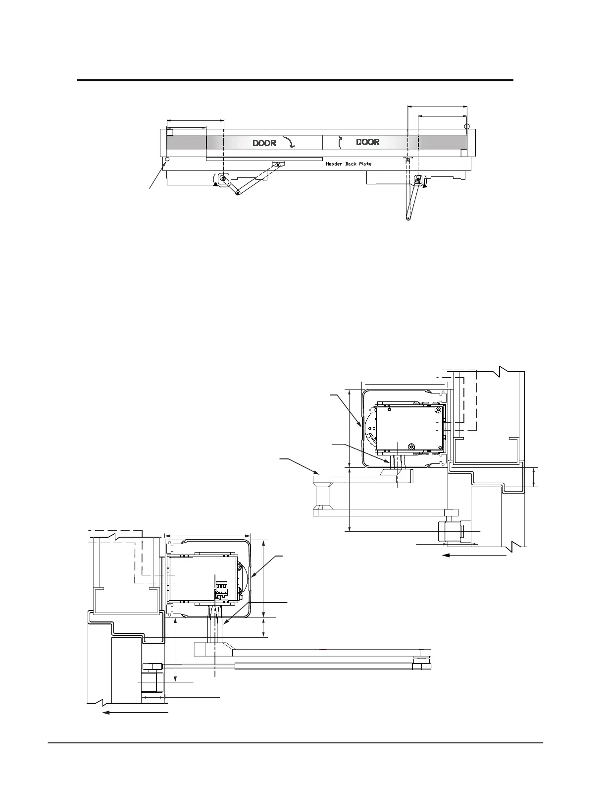
Double Egress Application Installation
16 1/8” [410]
12 3/16” [310]
”8/50
10 5/8” [270]
”4/12
Butt Hung & Offset Pivot
1) Determine the handing of the operators according to
the door. Note that arrow on operator indicates
opening direction of rotation.
2) Locate & mark output shaft locations as shown above,
for both operators.
3) Determine header mounting height. If both operators are
in a single header then mount the operators at 1-1/8”
from top of the door as shown below for In-Swing operator.
4) Secure header to the wall with appropriate hardware.
5) Locate and mount door arm and slide track onto the
doors at dimensions listed above.
6) Insert shaft/ drive arms into the operators, leave shaft
bolts loose until appropriate step during commisioning
procedure.
7) Proceed to page 20 to check or connect sync cable and
additional wiring.
C/L of
Pivot
5" [127]
REVEAL DISTANCE FROM THE
FACE OF THE DOOR TO THE
REAR OF OPERATOR
0"-9 7/8" (0-251)
3 9/16" [90]
4 9/16" [116]
1 1/8" [29]
SWING DIRECTION
C
L
Electrical
Controls
Access
Cover
SWING
DOOR
TORMAX
1102, 1201
OPERATOR
C
L
TORMAX
1102, 1201
OPERATOR
5" [127]
4 9/16" [116]
1 1/8" [29]
Electrical
Controls
Access
Cover
SWING DIRECTION
SWING
DOOR
C
L
3 3/4” [95]
REVEAL DISTANCE
FROM THE FACE OF
THE DOOR TO THE
REAR OF OPERATOR
0"-6" (0-152)
0 - 6”” Reveal Door Arm
141133 R.H.Shown
141134 L.H.Not Shown
Out-Swing Operator
In-Swing Operator
Standard D.E. Shaft 141106
3 15/16” (100mm)
Standard
Shaft 141032
3 7/32” (82)
 Loading...