37
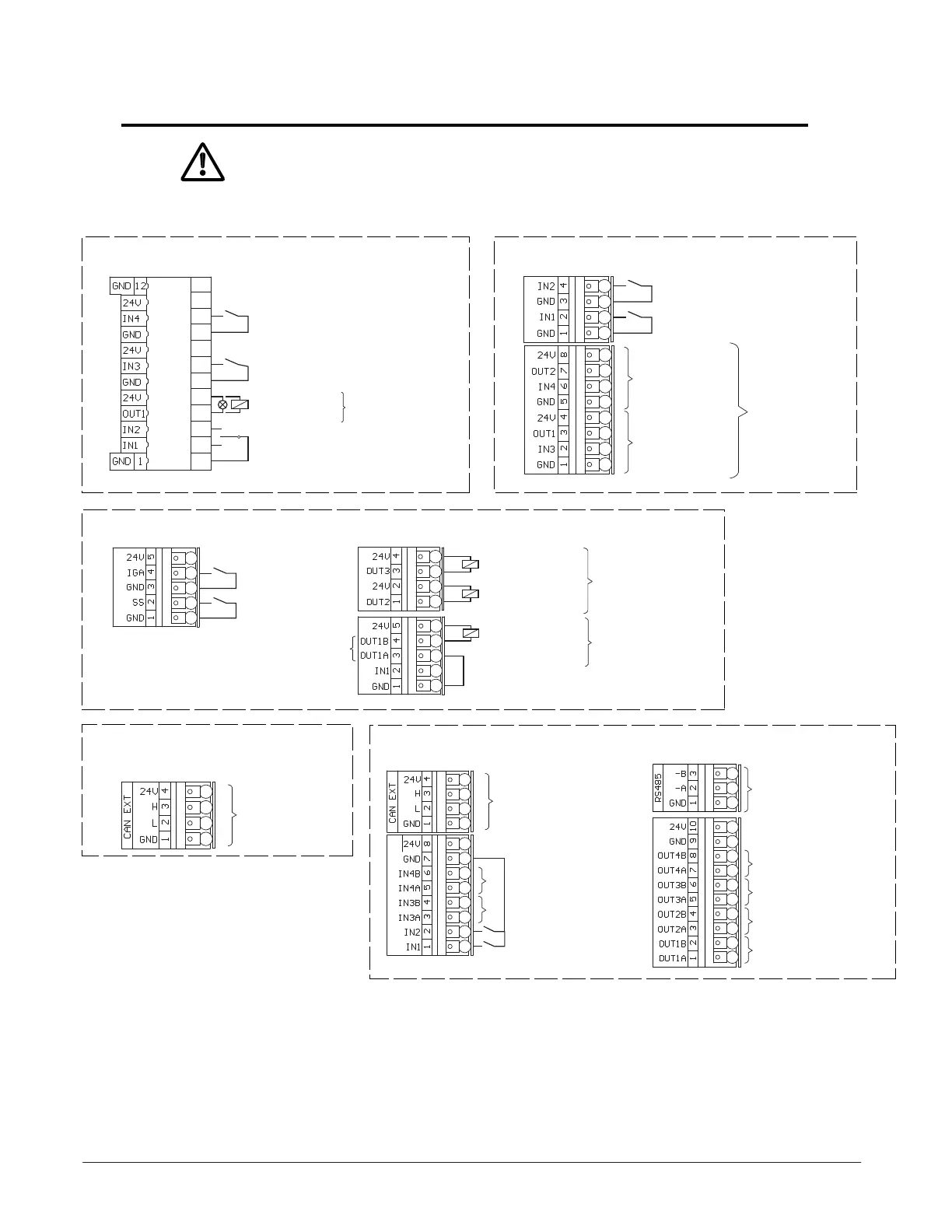
Control Connection Diagram
Connect components only with primary power removed (current-less).
Terminal Allocation in Default Programming
Base Module (BDM) Power Door Module (PDM)
A
Inhibit switch
No function
1)
Exterior Door Module (EDM)
T1655_3e
A
Key switch
Sensor
outside
Multi Door Module (MDM -B)
1) Function programmable
2) OUT 1A & OUT 1B are Normally Open dry contact
Load on power supply 24 VDC max. 1.5 A/36 W
B
A
D
C
T1655_4e
Networking
Double door
IN4 Passage for beds
1)
IN3 Op. mode EXIT
1)
IN2 Op. mode OPEN
1)
IN1 Op. mode OFF
1)
OUT4 Message
“Door operational”
1)
OUT3 Message
“Door closed and locked”
1)
OUT2 Message
“Door closed”
1)
OUT1 Message
“Door open»
1)
C
T1655_2e
Safety closing
1)
Safety opening
1)
T1655_1e
A
12
11
10
9
8
7
6
5
4
3
2
1
OPEN
Sensor inside
Error message
3-Pos. switch
AUTO
Safety
swing area
1)
OFF
OUT1
24 VDC/ max. 1 A
self resetting
OUT1-2 / GNDct
max. 1 A
self resetting
B
C
Holding magnet
Bell
Electric Lock
Code 57?(0, 1, 2)
Jumper required
for Electric Lock
OUT1/ OUT3
24 VDC/ max. 1 A
self resetting
OUT1 A/B
potential free
max. 1 A (at
68 ˚F)
< 40 VDC, 30 VAC
self resetting
A
Double door
Multi Door Module (MDM -A) - (Non Stocking part, special order)
2)
 Loading...