17
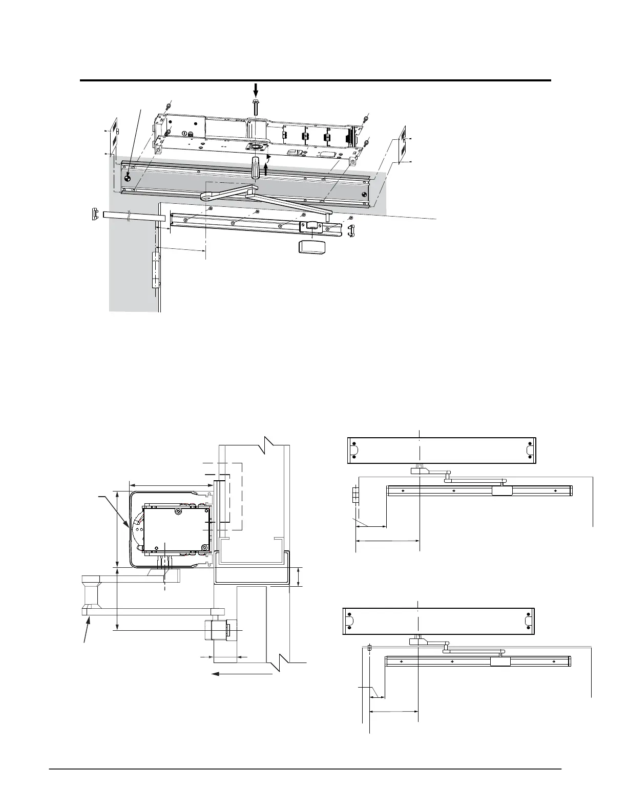
Inswing (Pull) Arm 0 - 6” Reveal Installation
1) Determine the handing of the operator according
to the door. Note that arrow on operator indicates
opening direction of rotation.
2) Locate & mark output shaft location as shown
below from CL of hinge or pivot onto door frame.
3) Mark header mounting height of 1 1/8” from the top
of the door as shown below.
4) Secure header to the wall with appropriate hardware.
5) Locate and mount door arm slide track onto the door at 3 3/4”
from bottom of the header and at the dimensions listed below
for the application.
6) Insert shaft/ drive arm into the operator, leave shaft bolt loose
until appropriate step during commissioning procedure.
7) Proceed to page 18 to perform commissioning.
Primary
Power
See details below
Electrical
Controls
SWING DIRECTION
SWING
DOOR
Access
Cover
TORMAX
1102, 1201
OPERATOR
5" [127]
4 9/16" [116]
1 1/8" [28]
REVEAL DISTANCE
FROM THE FACE OF
THE DOOR TO THE
REAR OF OPERATOR
0"-6" (0-152)
C
L
3 3/4” [95]
10-5/8” [270]
1-1/4”
[32]
C/L
Pivot
Butt Hinge
Header
9-7/16”[240]
2-1/4”
[57]
C/L
Pivot
Center Pivot
Header
C/L
Shaft
C/L
Shaft
0 - 6”” Reveal Door Arm
141133 R.H.Shown
141134 L.H.Not Shown
 Loading...