AdjustingtheGageWheels
1.Removetheboltandnutsecuringthegagewheelto
themower-deckbrackets(Figure29).
2.Aligntherollerandspacerwiththetopholesinthe
bracketsandsecurethemwiththeboltandnut.
CheckingaMismatchBetween
MowerDecks
Duetodifferencesingrassconditionsandthecounterbalance
settingofthetractionunit,youshouldcutthegrassandcheck
theappearancebeforeyoubegincuttingtheentirearea.
1.Setallmowerdeckstothedesiredheightofcut;refer
toAdjustingtheHeightofCut(page26).
2.Checkandadjustfrontandreartirepressure.
Note:Thecorrectairpressureinthefronttiresis345
kPa(50psi)andthereartiresis207kPa(30psi).
3.Checkandadjustallcastortirepressuresto345kPa
(50psi).
4.Checktheliftandcounterbalancepressureswithengine
atHIGHIDLEusingthetestports;refertoInspecting
theHydraulic-SystemTestPorts(page57).
5.Checkforbentblades;refertoCheckingforaBent
Blade(page60).
6.Cutgrassinatestareatodetermineifallmowerdecks
arecuttingatthesameheight.
7.Ifyouneedtoadjustamowerdeck,ndaatsurface
usinga2m(6ft)orlongerstraightedgetoensurethat
thesurfaceisat.
8.Toeasemeasuringbladeplane,raisetheheightofcut
tothehighestposition;refertoAdjustingtheHeight
ofCut(page26).
9.Lowerthemowerdecksontotheatsurfaceand
removethecoversfromthetopofthemowerdecks.
SideMowerDecks
1.Rotatethebladeofeachspindleuntiltheendsface
forwardandbackward.
2.Fortheoutsidebladespindleonly,equallyadjustthe
shimsonthefrontcasterforkstomatchthedesired
heightofcut.
3.Measurefromtheoortothefronttipofthecutting
blade.
4.Rotatetheblade180°andmeasurefromtheoorto
thetipofthecuttingblade.
Note:Therearofthebladeshouldbe7.5mm(0.3
inch)higherthanthefront.
Note:Ifyouneedtomakeanadjustment,adjustthe
shimsontherearcasterforks.
MatchingtheHeightofCutBetween
MowerDecks
1.Positionthebladesidetosideontheoutsidespindle
ofbothsidemowerdecks.
2.Measurefromtheoortothetipofthecuttingedge
onbothunitsandcomparethemeasurements.
Note:Thesenumbersshouldbewithin3mm(1/8
inch)ofeachother.Makenoadjustmentatthistime.
3.Positionthebladesidetosideontheinsidespindle
ofsidemowerdeckandthecorrespondingoutside
spindleofthefrontmowerdeck.
4.Measurefromtheoortothetipofthecuttingedge
ontheinsideedgeofthesidemowerdecktothe
correspondingoutsideedgeofthefrontmowerdeck
andcompare.
Note:Thesidemower-deckcasterwheelsshould
remainonthegroundwithcounterbalanceapplied.
Note:Ifyouneedtomakeanadjustmenttomatch
thecutbetweenthefrontandsidemowerdecks,make
themtothesidemowerdecksonly.
5.Iftheinsideedgeofthesidemowerdeckistoohigh
relativetotheoutsideedgeofthefrontmowerdeck,
remove1shimfromthebottomofthefront,inside
casterarmonthesidemowerdeck(Figure31and
Figure32).
Note:Checkthemeasurementbetweentheoutside
edgesofbothsidemowerdecksandtheinsideedge
ofthesidemowerdecktooutsideedgeofthefront
mowerdeckagain.
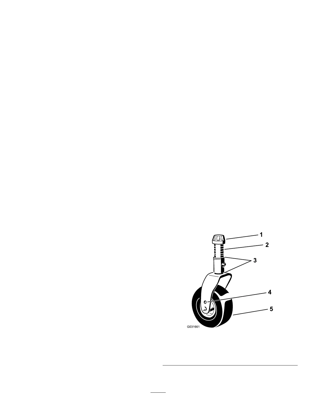
Figure31
1.Tensioningcap4.Topaxle-mountinghole
2.Spacers(6)5.Casterwheel
3.Shims(2topand2bottom)
29