ServicingtheCasterWheels
andBearings
ServiceInterval:Every500hours—Inspectthemower-deck
caster-wheelassemblies.
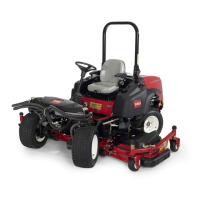
1.Removethelocknutfromtheboltholdingthe
caster-wheelassemblybetweenthecasterforkorthe
caster-pivotarm(Figure97).
Figure97
1.Casterwheel
3.Bearing
2.Casterfork
4.Bearingspacer
2.Graspthecasterwheelandslidetheboltoutofthe
forkorpivotarm(Figure97).
3.Removethebearingfromthewheelhubandallowthe
bearingspacertofallout(Figure97).
4.Removethebearingfromtheoppositesideofthe
wheelhub(Figure97).
5.Checkthebearings,spacer,andinsideofthewheelhub
forwear.
Note:Replaceanydamagedparts.
6.Toassemblethecasterwheel,pushthebearinginto
thewheelhub.
Note:Wheninstallingthebearings,pressontheouter
raceofthebearing.
7.Slidethebearingspacerintothewheelhubandpush
theotherbearingintotheopenendofthewheelhub
tocaptivatethebearingspacerinsidethewheelhub.
8.Installthecaster-wheelassemblybetweenthecaster
forkandsecureitinplacewiththeboltandlocknut.
BladeMaintenance
BladeSafety
DANGER
Awornordamagedbladecanbreak,andapiece
ofthebladecouldbethrownatyouorbystanders,
resultinginseriouspersonalinjuryordeath.
Tryingtorepairadamagedblademayresultin
discontinuedsafetycerticationoftheproduct.
•Inspectthebladeperiodicallyforwearor
damage.
•Nevertrytostraightenabladethatisbentor
weldabrokenorcrackedblade.
•Replaceawornordamagedblade.
•Usecarewhencheckingtheblades.Wrapthebladesor
weargloves,andusecautionwhenservicingtheblades.
Onlyreplacetheblades;neverstraightenorweldthem.
•Onmulti-bladedmachines,takecareasrotating1blade
cancauseotherbladestorotate.
CheckingforaBentBlade
Afterstrikingaforeignobject,inspectthemachinefor
damageandmakerepairsbeforerestartingandoperatingthe
equipment.Torqueallthespindle-pulleynutsto176to203
N·m(130to150ft-lb).
1.Positionthemachineonalevelsurface.
2.Raisethemowerdeck,engagetheparkingbrake,put
thetractionpedalinNEUTRAL,makesurethatthe
PTOswitchisintheOFFposition,shutofftheengine,
andremovetheignitionkey.
3.Blockthemowerdecktopreventitfromaccidentally
falling.
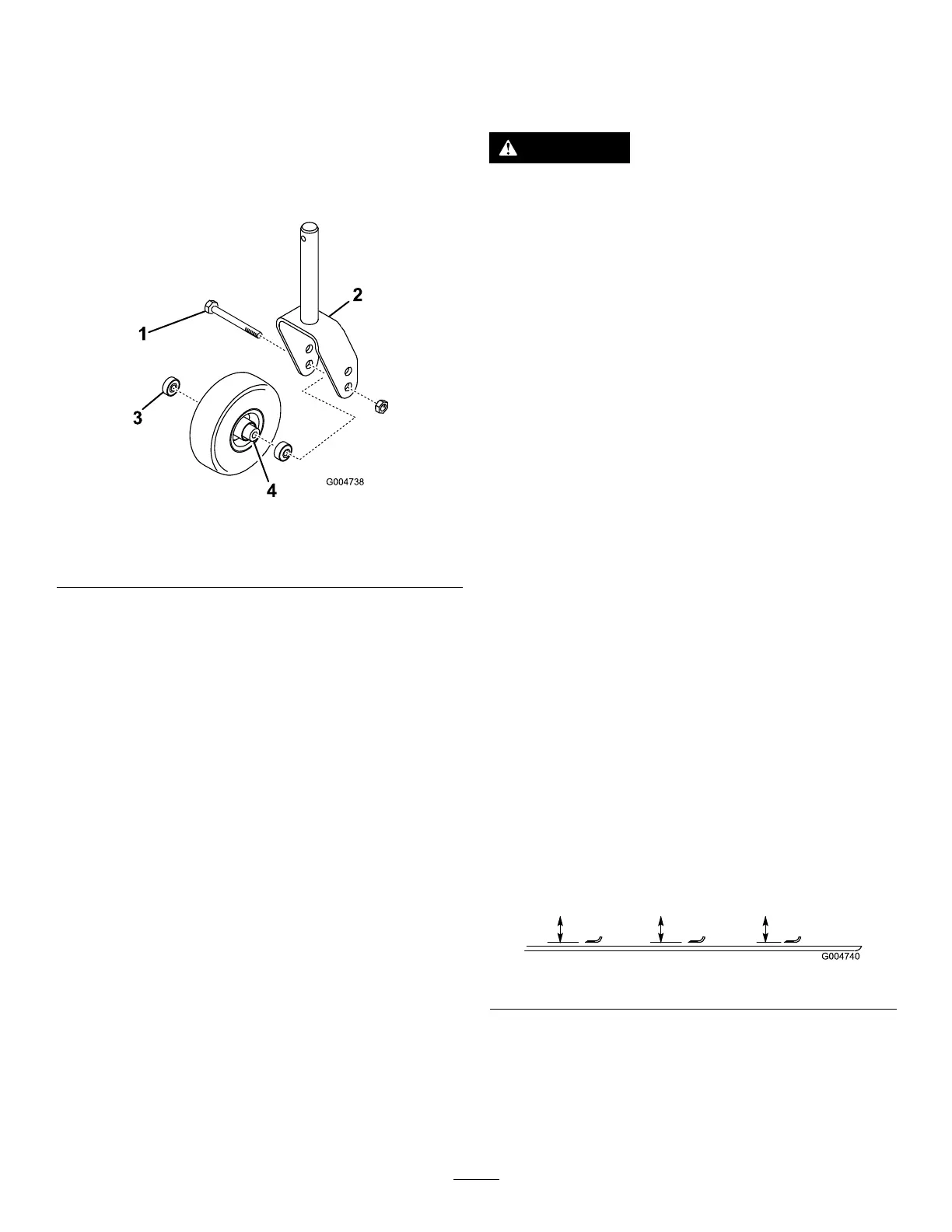
4.Rotatethebladeuntiltheendsfaceforwardand
backward,andmeasurefromtheinsideofthemower
decktothecuttingedgeatthefrontoftheblade
(Figure98).
Note:Recordthisdimension.
Figure98
5.Rotatetheoppositeendofthebladeforwardand
measurebetweenthemowerdeckandcuttingedgeof
thebladeatthesamepositionasinstep4.
Note:Thedifferencebetweenthedimensions
obtainedinsteps4and5mustnotexceed3mm(1/8
inch).Ifthedimensionexceeds1/8inch(3mm),the
60