g020875
Figure82
1.Bolts
2.Controlpanel
4.MovethecontrollevertotheNEUTRALposition
butnotlocked(Figure84).
5.Pulltheleverbackuntiltheclevispin(onan
armabovethepivotshaft)contactstheendof
theslot(justbeginningtoputpressureonthe
spring)asshowninFigure83.
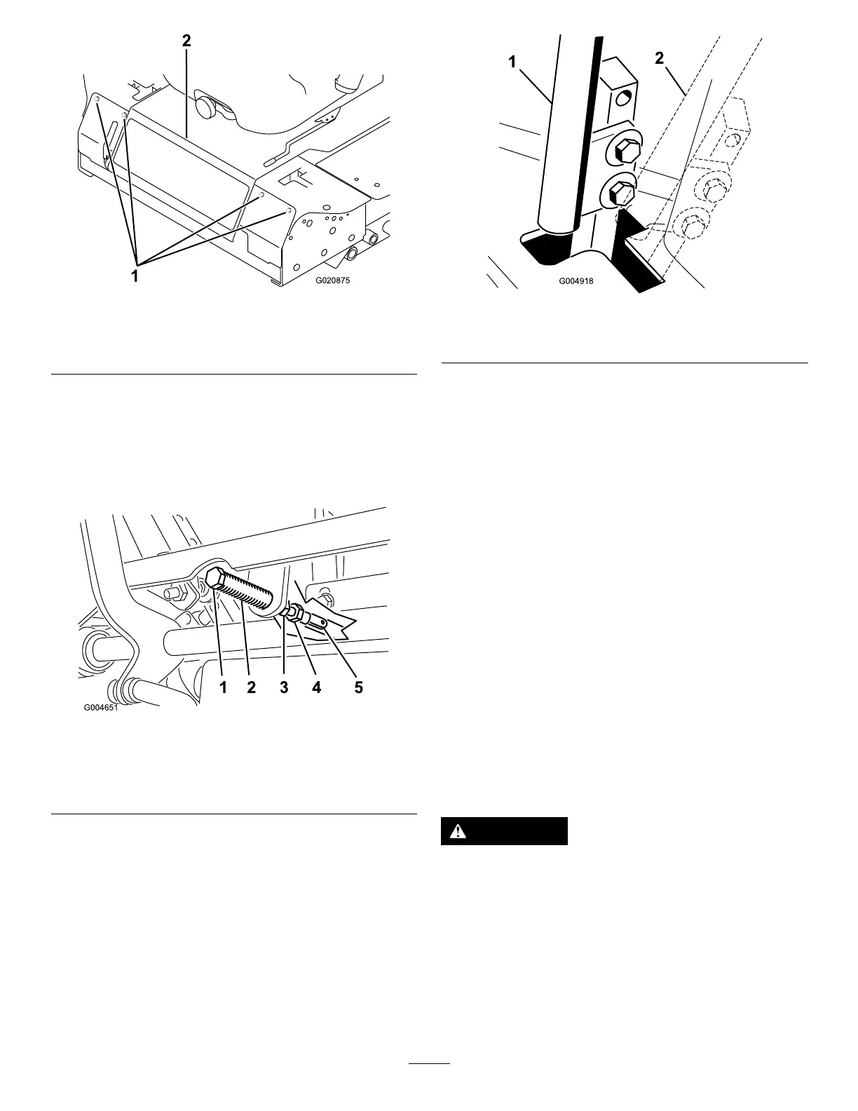
g004651
Figure83
1.Clevispin
4.Adjustmentbolt
2.Slot
5.Yoke
3.Jamnuts
6.Checkwherethecontrolleverisrelativetonotch
inconsole(Figure84).
Note:Thecontrollevershouldbe
centered,allowingittopivotoutwardtothe
NEUTRAL-LOCKEDposition.
g004918
Figure84
1.Neutralposition2.Neutral-lockedposition
7.Ifadjustmentisneeded,loosenthenutandjam
nutagainsttheyoke(Figure83).
8.Applyingslightrearwardpressureonthe
motion-controllever,turntheheadofthe
adjustmentboltintheappropriatedirection
untilthecontrolleveriscenteredinthe
NEUTRAL-LOCKEDposition(Figure83).
Note:Keepingrearwardpressureonthelever
keepsthepinattheendoftheslotandallows
theadjustmentbolttomovethelevertothe
appropriateposition.
9.Tightenthenutandjamnut(Figure83).
10.Repeatsteps4through9fortheothercontrol
lever.
11.Installthefrontpanel.
AdjustingtheTraction
DriveforNeutral
Thisadjustmentmustbemadewithdrivewheels
turning.
DANGER
Mechanicalorhydraulicjacksmayfailto
supportthemachineandcauseaserious
injury.
•Usejackstandswhensupportingthe
machine.
•Donotusehydraulicjacks.
63